This thread has been locked.

If you have a related question, please click the "Ask a related question" button in the top right corner. The newly created question will be automatically linked to this question.

TPS61288: Vin=6v-8.4 V vout =12v 2.5 ampere ,IC is not turning load again once load disconnected

Part Number: TPS61288

Hi,

We are working with tps61288 

and giving input 6V-8.4V lithium battery and Vout is =12V /2.5 amp

we have made the circuit in such a way that If the Vin falls below 6v the output turn off and when comes above 7.4V the output comes again ,this is controlled through a mosfet at the output of the boost convertor .

The problem we are facing here is once the mosfet is turned off that is the output disconnected when we increase the input voltage the boost IC is not reviving the voltage again .

if we do same process without output load that is through electronic load at 2.5 ampere the output comes above 7.4 and cuts below 6v.

Why is the boost ic not making voltage at load connected the voltage drops until we increase the voltage all the way upto to 8.4v.

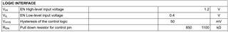
Also please tell us the EN pin specifications .(its high logic voltage,disable low logic voltage and maximum voltage)

thanks

  • Hi zuhaib,

    Could you share your schematic?

    Also, I'm not so clear about below description.

    The problem we are facing here is once the mosfet is turned off that is the output disconnected when we increase the input voltage the boost IC is not reviving the voltage again .

    What is the output voltage of the device when MOS is disconnected?

    if we do same process without output load that is through electronic load at 2.5 ampere the output comes above 7.4 and cuts below 6v.

    The device works as you designed(shut below 6V and restart at 7.4V) when load always is 2.5A, is it right?

    For the EN spec, please see below in datasheet,

    Regards,

    Fergus

  • below 0.4v enable is low above 1.2V enable is hight but upto what voltage? what is the max voltage of EN pin?

    2nd 

    Let me be precise

    We give input from 6-8.4V 

    Boost output is 12V and the load connected is 2.5 ampere.

    VIN=8.4 Vout boost =12V load connected 2.5 ampere ok.

    VIn is varied now from 8.4 to 6 V boost comes 11.70V 2.5 amp ok.

    (Voltage falls below 6V output  cuts through our mosfet mechanism)

    When we increase voltage again the boost output not coming 12V the output drops if we keep load connected the boost voltage is coming 6.5V 2.5 ampere and voltage is increased to 8.4 Vout comes 10.6V 2.5 ampere also some audible noise coming from the IC .

    If we turn off and turn on the load the.

    basically if the battery is discharged and then again charge and the load is connected boost IC will only perform until we disconnect and connect the load again.

  • Hi zuhaib,

    The max voltage of EN is 6V.

    It looks that something changes when you increase the voltage again.

    Could you have a test of the waveform about the process?

    And schematic is preferred.

    Regards,

    Fergus

  • We have find the root cause and that is the output capacitor when we put higher capacitor value the circuit dont turn on from off state when load is connected.

    We have two designs 

    Vin=6-8.4V Vout=12V_2.5 works on 100uf electrolytic capacitor with keeping 3 *22uf ceramic capacitors. it turn on and off on load but if we increase the output capacitor the IC dont work on load connected.

    2.

    In Vin=3-4.2V Vout=5V_2.5 works on 680uf electrolytic capacitor with keeping 3 *22uf ceramic capacitors. it turn on and off on load but if we increase the output capacitor the IC dont work on load connected.

    Please help in solving this issue why the IC is not working same with higher capacitance values?

    I am sharing the schematic with the pcb design as well.

  • Hi zuhaib,

    From the schematic, it looks that the device does not get enough margin at the condition 6Vin 12Vout and 2.5A.

    Please see the calculation tool.

    you can decrease the Rcomp to 10k to gain a more stable loop.

     1121.TPS61288 Calculation tool.xlsx

    For the Vin=3-4.2V Vout=5V_2.5, the situation is the same, you can fill in the parameters to see the Phase and Gain Margin.

    It is also recommended to decrease Rcomp to 10k.

    The PCB looks all ok.

    Please have a try and I will wait for the feedback.

    Regards

    Fergus

  • I have tried it I have changed the Rcomp from 100k to 10k the boost rise slowly and finally makes 4.9V .

    Now giving load 2.5 Amp now decreasing and increasing the voltage again the boost voltage drops at load being connected.

    Its not working .

    .

    The calculator shows the same values I have used then Why its not working?

  • I have used 68 pf instead of 680 pf does it make any difference?

  • Hi zuhaib,

    1. it seems that changing Rcomp has little influence, right?

    Is 4.9V just the target of your output? (You said the target is 5V, but I'm not sure)

    When adding 2.5A, you mentioned that the output drops, could you have a check if the input voltage also drops to trigger the UVLO protection?

    2. Changing 680pF with 68pF will make some difference with the loop.

    The point is, I'm not sure if your problem is related to loop.

    Could you have a waveform of the input and output wave when connecting to 2.5A load?

    This may help us to clarify the question.

    Regards

    Fergus