Hello,
I designed a board with a BQ76952 with a 0805 SMD footprint to place (or not) a 0 ohm resistor between C1N and BAT-.
According to me, this resistor should not be soldered. The hi-current should flow using the BAT- wire and the C1P return current should flow using C1N wire. This is the only way to correctly measure the C1 level without being perturbated by the voltage drop accross the wiring.
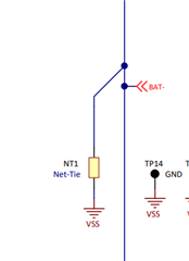
Using a net tie between C1N and BAT-, the battery current will flow using both BAT- and C1N wire, causing a voltage drop accross C1N wire (between the battery and the PCB net tie).
However, the BQ76952EVM is using a non-removable net-tie between C1N and BAT-. This design is mentionned in the device data sheet as a typical implementation.
So, what should be done and why?
Thank you,
Regards