Hi TI support team,
We are designing solution with LM5176RHF, for buck-boost wide input range scenario.
During our load transient test, we met some oscillation at output when in 9V boost mode. So could you help to check the COMP and slope circuit if properly set?
**************************************
Design parameter:
INPUT: 9V~36V.
OUTPUT: 12V
MAX current(avg.): 12A
OCP SETTING: 17A
*************************************

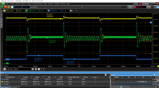
yellow: input 9V
green: output.
blue: load current.
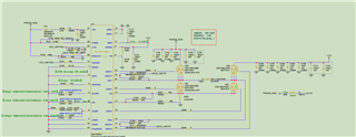
schematic:
Thanks in advance
Zack