This thread has been locked.

If you have a related question, please click the "Ask a related question" button in the top right corner. The newly created question will be automatically linked to this question.

UCC28782: High side FET ON time becomes longer.

Part Number: UCC28782

Check the waveform below.
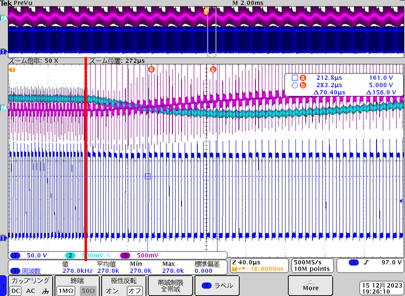
CH1 (blue) is the Vds of the low side FET.

The ON time of the high side FET becomes longer in an instant from the red line part.

The ON time of the high side FET continues to be long, the output voltage (CH2: light blue) decreases, and the voltage between the collector and emitter of the photocoupler (CH3: purple) increases.

I changed the resistance values of RTZ and RDM by ±10%, but there was no change in operation.

Can you think of any reason why the ON time of the high side FET becomes longer in an instant?

I've made over 500 units so far, and only one has had this problem.

  • Hi Takuya-San,

    Thank you for the query on UCC28782.

    I think it is really hard to comment on this.

    For the UCC28782 controller, duty cycle is actually set by controlling the peak primary current (peak current-mode control) to an internal current-sense threshold voltage (Vcst).
    The PWML signal is set high at the beginning of a switching cycle and stay high until the voltage at the CS input exceeds the internal threshold.  The Vcst itself is modulated by the current pulled out of the FB pin, based on the device's Control Law. 

    The PWMH signal, which drives the active-clamp transistor, is also indirectly modulated based in part on the demagnetization time (determined by the peak primary current, the output voltage, and the turns ratio) and in part by any additional time needed to generate negative magnetizing current based on the input voltage. Since you did not observe any effect by changing the RTZ and RDM, I suspect it could be due to noise from the FB/CS signals which is causing the controller to experience this sudden changes in ON time. 

    What is the condition at which you observe this issue- Input voltage and load condition?

    Regards,

    Harish

  • In the entire input range, there is no problem in operation up to LPM, but an abnormal operation occurs from the moment it enters ABM.

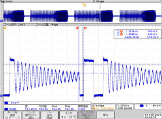
    The above waveform is the VDS waveform of the Low-Side FET in the ABM operation area of the IC where this problem occurs.

    The ON time of High-Side FET is rapidly increasing compared to the previous ON time.

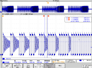
    The waveform after a few μs of the above waveform is as shown below, and the number of SW operations changes from 2 to 5, and finally AAM operation is performed.

    If this defective IC is installed in a normally operating power supply, the above defect symptoms will occur.

    Therefore, we believe that there is no noise factor.

    If it is a noise factor, what countermeasures can be considered?

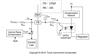
    The circuit configuration of the FB pin is similar to the recommended circuit (see below).

    Also, Cfb is located close to the IC on the board, so it is difficult to get it any closer.

    The waveforms during AAM operation in the IC where this problem occurs are shown below.

    In AAM operation, the ON time of the High-Side FET changes suddenly in the red line area, just like in ABM, and the operation becomes unstable.

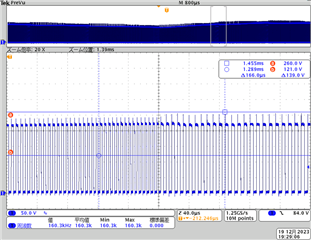
    Next, the waveforms of the Low-Side FET's Vds and CS terminal (≒Low-Side FET drain current) when DC130V is input are shown below.

    Even if the ON time of the Low-Side FET suddenly changes, the peak value of the drain current will not change.

    If the FB pin changes due to noise, etc., the drain current peak value also changes, so there is no possibility that the FB pin changed due to noise.

    Best Regards,

    Takuya Aoki

  • Hi Takuya-San,

    I agree that it might not be due to noise on FB as I had initially thought off.

    So on the issue of operation being stable upto the LPM region, I think there could a possibility there is some unstability at the boundary while toggling between LPM and ABM. Can you please check if the ΔVBUR(LPM) is designed greater than 100mV. When VBUR steps higher on transition into ABM from LPM, the initial peak magnetizing current in ABM is decreased with smaller energy per switching cycle. This potentially could decrease the output voltage. Similiar thing needs to be check for transition from ABM to AAM mode.

    Secondly (I am not saying this as the cause but you could verify this ) the RDM resistor should provide the power stage information to the optimizer inside for auto tuning of PWMH signal to achieve ZVS. As RDM is a function of magnetizing inductance, Rcs and turns ratio. Since most our your units are working (49/50) could you check if there are any big tolderance in the transformer inductance which might cause this effect. 

    Thank you

    Regards,

    Harish

  • Hi Harish,

    I design ΔVBUR(LPM) to be 100mV or more. Additionally, ΔVBUR (AAM) is designed to be 150mV or more.

    I replaced the transformers of the product that was working normally and the product that was working abnormally, but there was no change in the operation, and I have confirmed that there is no difference in the inductance value of the transformer.

    Best Regards,

    Takuya Aoki

  • Hi Takuya-San,

    Thank you for the reply.

    You probably might check the following document which suggests adding hysteresis while transitioning between modes. 

    8270.BUR hysteresis circuitry to Eliminate ABM-AAM transition (Audible Noise) .pdf

    I am not sure this is going to be solution to this particular board, but could be tried as all your other boards are working without any problem. This could be due to part to part variations between the components. You might also consider trying with any other UCC28782 IC from the other boards, just in case to discard this as a cause.

    Regards,

    Harish

  • Hi Harish,

    Hysteresis is still added at this time.

    Also, as I reported last time, ABM operation is not entered during AAM operation, but since it is an abnormal operation, I think that hysteresis and Vbur design are not related.

    This suggests that the cause may be due to variations in parts between components, but as shown in the table below, this abnormal operation occurs only when an IC that behaves in question is installed.

    Best Regards,
    Takuya Aoki

  • Hi Takuya-San,

    I think there could be some abnormality with this particular IC or it has some damage. We would recommended swapping this IC with a new one.

    Thank you'Regards,

    Harish

  • Could you please analyze what is wrong with this particular IC?

    I think there is a possibility that the same problem will occur in the future, so I would like to fully understand the cause.

  • Hi Takuya-San,

    I checked earlier today with the EVM board but it does not seem to have this issue. Maybe I can try with a few more samples to see if can replicate this issue.

    Thank you

    Regards,

    Harish