This thread has been locked.

If you have a related question, please click the "Ask a related question" button in the top right corner. The newly created question will be automatically linked to this question.

TPS92200: Two TPS92200D2 in parallel

Part Number: TPS92200
Other Parts Discussed in Thread: TPS922055, TPS922054

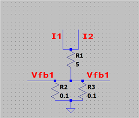
I connected two LED driver is parallel, as shown in the schematic.
Like before I expected a total of 1[A] through the resistor, as per this equation:

I = I1 = I2
Vfb = Vfb1 = Vfb2
R2//R3 = R4
Rt = R1 + R4 = 5.05
U = I * Rt = (I1 + I2) * 5.05

Vfb = U * (R4/Rt) = 0.099 (according to the datasheet the reference voltage will be 99[mV] at VDIM 3.21[V]

Vfb = ((I1 * I2) * Rt) * (R4/Rt) = 2 * I * 0.05 = 0.099[V]

I = 0.99[A], so about 1[A]

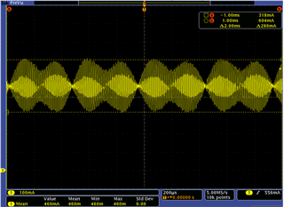
In practice I indeed get around 0.906[mA], which makes sense due to loss and my PWM is 95%.
However, what I find remarkable is the Vfb. I measure 0.056[V] instead of 0.099[V]. I expected this to be close as the PWM is 95%

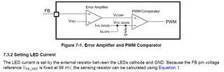
Shouldn't the TPS92200D2 increase the current till it reaches 0.099[V] on the Vfb?

I guess I could lower the R4 to see if the current increases and Vfb stays 0.056[V].

  • I checked with 100% duty cycle as well and the Vfb is still 0.056[V]. VDIM = 3.3[V]

  • I might have misinterpreted the datasheet.

    Maybe VREF = VFB_REF and so the voltage on the FB pin is not 99[mV]. Still I would expect the opamp to push it to 99[mV]

    I connected the resistor directly to GND instead of the Vfb (FB pin 1). The voltage on FB is 0[V], so I guess as it is not exceeding the 140[mV] it will not get into voltage protection mode.
    Still the maximum current is less then 1[A]. How can I increase the current? With the resistor directly connected to GND I would expect 1.5[A] per driver. And maybe even get an over current protection error.

  • Hmm I forgot this is a BUCK LED driver the output on the load can't exceed the 5[V] input and therefore no more then 1[A] of current is consumed with the 5Ohm load. Decreasing the resistance increased the current, and it seems that connecting two LED driver in parallel, to divide the current is okay. Both DIM pins are connected to the same PWM.

    @TI could you confirm that connecting the LED driver in parallel is okay?

  • I didn't realize this a few hours ago, but I found that individually the wires I1 and I2 are controlling the current inverse of each other. So measuring the cables combined, the current is smooth. However, measuring on wire the current fluctuates a lot, so is constantly controlling to compensate the other controller.

    I assume this will give some EMI/EMC issues, so this seems to be not a good idea.

  • Hi LucEE,

    You cannot connect the output of two TPS92200 in parallel.

    May I understand why you need to do this? What are your input voltage, output voltage and output current requirements? 

    Best Regards,

    Steven

  • Hi Steven,

    Well, no specific requirements yet. Just looking wat would be possible. I now know that connecting two in parallel is not possible so I have to do with either two separate loops of heaters, or just one and except that maximum output.
    Thank you for your reply

  • Hi LucEE,

    You are welcome. For a larger output, you can take a look at TPS922054 / TPS922055.

    Best Regards,

    Steven