Because of the holidays, TI E2E™ design support forum responses will be delayed from Dec. 25 through Jan. 2. Thank you for your patience.

This thread has been locked.

If you have a related question, please click the "Ask a related question" button in the top right corner. The newly created question will be automatically linked to this question.

TPS65988EVM: DisplayPort 1.4 input (from DP source) and USB PD input (from AC adapter) to one USB-C output (DP ALT + USB PD)

Part Number: TPS65988EVM

Hi,

I am hoping to use the TPS65988EVM board to evaluate our use case of connecting a DisplayPort source + USB-PD source (20V) and have it output on one USB-C connector (to a DP ALT and USB PD compliant sink).

Based on the documentation of TPS65988EVM, it seems possible to do each one independently (connect a USB-C PD source and USB-C PD sink for power delivery, and DisplayPort source to DisplayPort over type-C sink), but I was wondering if TPS65988 would be able to handle and negotiate for both operations simultaneously. Please see below for a block diagram. 

Thanks!

Brian

  • Hi Brian,

    Yes, the EVM is capable of acting as a DP source and acting as a USB-PD source simultaneously.

    Thanks and Regards,

    Chris

  • Hi Chris,

    Thank you for confirming. I have my TPS65988EVM now, but I am having a bit of trouble getting port 2 (source) to advertise and deliver a PD profile to my sink (stuck at 5V/0.9A). The board is getting powered directly from port 1 (sink) at 20V/3A from an AC adapter.

    Connection flow - AC adapter -> port 1 (sink) -> TPS65988 -> port 2 (source) -> sink device

    I have configured GPIO14/15 correctly in the GUI. Upon checking CC logs, it does not look like the port 2 (source) of TPS65988 is correctly advertising any PDOs above 5V/0.9A. The variable buck should be properly configured to provide any PD negotiated voltage (5V/9V/15V/20V). Is there any other lever I need to pull on the EVM to trigger this negotiation? Thanks

  • Hi Brian,

    Can you share the .pjt file you are using with the GUI? Can you also share the CC/PD logs?

    To make sure the Source port is advertising correctly, you are mainly interested in these 5 registers:

    1. Global System Configuration

        Make sure power paths are configured correctly, I would compare this to a default 988 source project in the GUI

    2. Port Configuration

        Check the Port Configuration field for DFP or DRP

    3. Port Control

       "Process Swap to Source" should be selected, and "initiate swap to sink" should not be selected

    4. Transmit Source Capabilities

        You should have Source PDOs for each voltage you want

    5. I/O config

        Check that the I/Os for Source PDOs match the User Guide

    If you have the sink side working, when connected, does 20V appear on the VSYS pin?

    What does your J11 configuration look like?

    If you have a 20-V barrel jack, you should be able to load one of the 988 DFP projects from the GUI and test source while powering the board from the barrel jack.

    Thanks and Regards,

    Chris

  • Hi Chris,

    Thank you for the thorough response. Please find the .pjt and PD/CC log file below. I am using port A as the source side (connected to sink device) and port B as the sink side (connected to AC adapter). I am able to confirm both sides working properly independently, but am having issues if I combine both and try to provide power from port A to port B.

    My J11 configuration is connecting PP_HV2 <--> SYS_PWR and PP_HV1 <--> A-VAR

    If I provide 20V directly onto SYS_PWR (via external power supply), I am able to source 20V from port A to my sink. If I connect the AC adapter to port B, I can see 20V on the SYS_PWR pin. 

    I found this thread below that is implementing something very similar, but even upon comparing .pjt files, I can not find any significant differences. https://e2e.ti.com/support/power-management-group/power-management/f/power-management-forum/1256776/tps65988dkevm-what-are-the-required-jumper-settings-for-a-dual-usb-c-port-product-that-receives-power-only-from-usb-c

    Please let me know if there's any additional information you need from me. Thanks!

     TPS65988_PortA_source_PortB_sink_test_files.zip

  • Hi Chris,

    Upon further digging, I think I found the root cause. Given I am providing power only through Port B, I believe TPS65988 is operating in a dead-battery state. If I enter debug mode and clear the dead-battery flag (with sink disconnected), and then re-connect the sink on Port A, I see TPS65988 is capable of sinking and sourcing the same 20V. 

    Is there any chance we could automatically clear the dead-battery flag within TPS65988 for our use case? Given both systems will not have a battery on board and we are hoping to use straight USB-C power for everything, is this something that could be bypassed?  

    In the meantime, to test on my TPS65988EVM, I am STUFFing R109 to connect BJ_DETECT to GPIO1 and repurposing GPIO1 to Barrel Jack Detect Event in the GUI. This way, When Port B is connected and negotiates to 15 or 20V, it will trip GPIO1, which automatically clears the dead battery flag. 

    Please let me know your thoughts. If there is a simpler way to clear the flag, I am all ears (would help a ton to not need the comparator and extra circuitry in our final design).

    Thanks!

    Brian

  • Hi Brian,

    Upon further digging, I think I found the root cause. Given I am providing power only through Port B, I believe TPS65988 is operating in a dead-battery state. If I enter debug mode and clear the dead-battery flag (with sink disconnected), and then re-connect the sink on Port A, I see TPS65988 is capable of sinking and sourcing the same 20V. 

    Yeah, this is likely the issues. When taking power off of VBUS (not internal power), we enter operation in "Dead Battery Mode" and set the DBFg. Source capability is limited to 5V sourcing in dead battery mode, so clearing the flag is a requirement.

    Is there any chance we could automatically clear the dead-battery flag within TPS65988 for our use case? Given both systems will not have a battery on board and we are hoping to use straight USB-C power for everything, is this something that could be bypassed?  

    In the meantime, to test on my TPS65988EVM, I am STUFFing R109 to connect BJ_DETECT to GPIO1 and repurposing GPIO1 to Barrel Jack Detect Event in the GUI. This way, When Port B is connected and negotiates to 15 or 20V, it will trip GPIO1, which automatically clears the dead battery flag. 

    Please let me know your thoughts. If there is a simpler way to clear the flag, I am all ears (would help a ton to not need the comparator and extra circuitry in our final design).

    The TPS65988 does not have native PD Passthrough, and can not update the "Transmit Source Caps" register with respect to the other ports active contract without an external MCU. The behavior of the dead battery flag helps prevent accidentally browning out the system by drawing too much power.

    You may need to take this into consideration when designing your system.

    One of the concerns with using the Barrel_jack event is that your sink port may attempt to do a PR_swap, making the system lose power. The event was intended for situations when internal power was applied to the system.

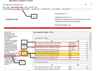
    A better option would be to use the "Port X Load App Config X Event" gpio events. You would keep the virtual address app config untouched to not change the configuration, and use the Dead Battery Flag Clear (DBFg) command on entry.

    I linked an App note that goes into the configuration of this feature.

    https://www.ti.com/lit/an/slvaf46a/slvaf46a.pdf?ts=1704729128153&ref_url=https%253A%252F%252Fwww.ti.com%252Fproduct%252FTPS65988

    Unfortunately, I do not see a way around the comparator hardware. You will still need some way to trigger a GPIO.

    Thanks and Regards,

    Chris

  • Hi Chris,

    Thanks a ton for the guidance and explanation, I am able to successfully use the app configuration register as you've suggested to clear the dead battery flag. We're proceeding with our design and I wanted to confirm whether the USB2 signals are required on TPS65988 if the BC1.2 feature is not used. Based on my testing, it should be OK if the USB2 signals are left NC on both ports, but please let me know your thoughts. Thanks.

  • Hi Brian,

    Yeah, the USB_DP and USB_DN pins on the device are only for BC1.2 support, and can be left NC if BC1.2 is not required.

    Thanks and Regards,

    Chris

  • Hi Chris, 

    Thank you for confirming for USB2! 

    I have been prototyping to use TPS65988EVM to source 20V over the external PP_EXT (PP3) path when the sink requests 20V. At all other voltages (5V, 9V, 15V), I would like to use the internal PP_HV1 switch instead, connected to the variable supply.

    In the configuration tool, I have PP3 selected as an output, GPIO16 multiplexed to PP3 alternate function, PP3 sourcing on the proper 20V PDO, and on the board, I've removed R27 (per schematic suggestion when using EXT path as a source path). 

    I haven't gotten it to come up yet, but is there anything in the config that I'm missing here? The motivation for this is to bypass the DCR losses through the high-side FET and inductor when we are sourcing and sinking 20V through the two ports. I know the EXT path is suggesting for sink only, but please let me know if there's any other considerations I need to take into account. 

    Thanks!

  • Hi Brian,

    It seems like you have the right idea. Can you monitor the voltages at these nodes and see what they do when you attempt to negotiate 20-V. Could you also share a PD log during the 20-V contract?

    Within the GUI, make sure you configure the PP3 as Source in Global System Configuration, and the Switch Source to PP3 in Transmit Source Capabilities.

    Thanks and Regards,

    Chris