A related question is a question created from another question. When the related question is created, it will be automatically linked to the original question.
If you have a related question, please click the "Ask a related question" button in the top right corner. The newly created question will be automatically linked to this question.
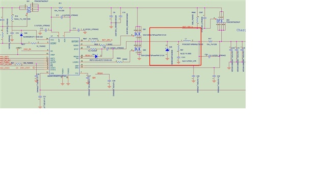
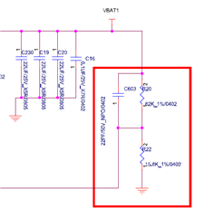
Overall, the schematic looks good. I do have one comment about the output capacitance below (~ 66.1uF)
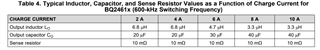
Please see the table below with recommended output capacitance values as a function of charge current. Moreover, the recommended resonant frequency range is between 12-17 kHz. With your current value of 66 uF, the LC output filter resonant frequency is 7.51kHz.
I recommend decreasing the capacitance to ~20uF to see if that resolves the jitter at the phase node.
Please let me know if you have additional questions/concerns.
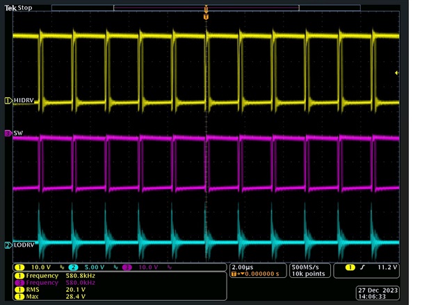
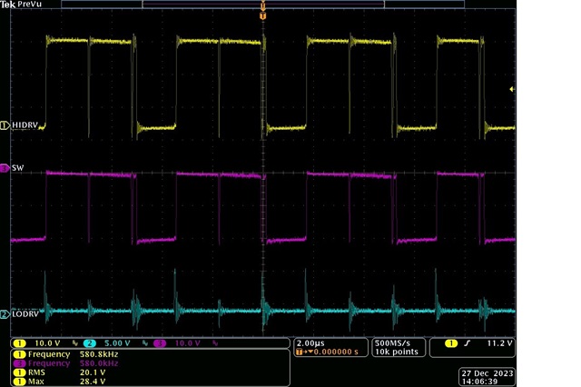
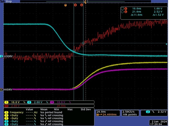
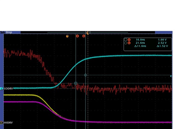
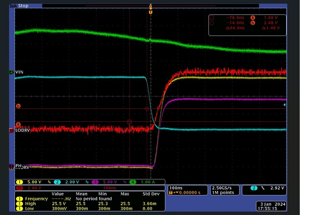
1.The customer also found that there is a problem of burning the upper and lower bridge MOS (FKBB3002). They have measured the waveform as shown in the attachment (Math=HIDRV-PH). Is there a risk to fix it though?
2.If the HIDRV and LODRV frequencies cannot be locked and the constant jitter causes the choke to be very hot, will it cause damage to the MOS?
Will the small dead time of HG and LG cause a shoot though?
How to adjust the dead time?
Adding the vin current (green) waveform, it seems that there is no shoot though
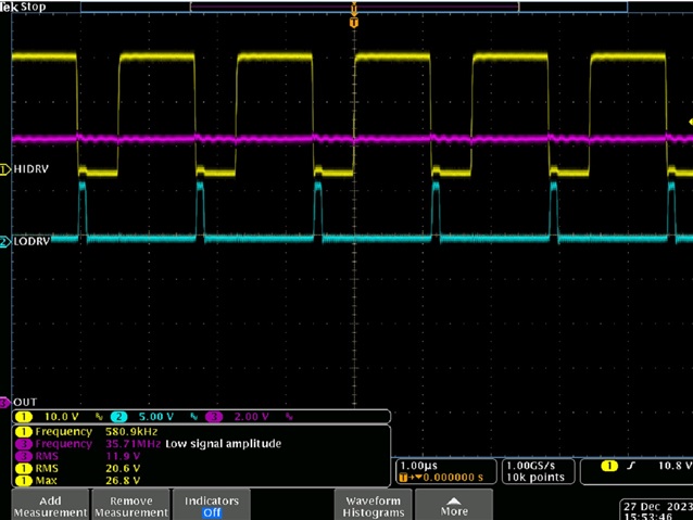
After adjusting C24, C29 and C30 to 0.22uF, the jitter has improved.The measured Rsense voltage is 26mV, but the LDRV waveform as shown below appearsThe schematic also removes D29 (Zener diode)Customer feedback that removing the output capacitor only has 22u is ineffective.
The charger operates in nonsynchronous mode when the SRP-SRN voltage is below 5 mV (0.5-A inductor current for a 10-mΩ sense resistor). Since the measured voltage is 26mV, the charger should not be in nonsynchronous mode.