This thread has been locked.

If you have a related question, please click the "Ask a related question" button in the top right corner. The newly created question will be automatically linked to this question.

BQ27531-G1: New Learning Cycle

Part Number: BQ27531-G1
Other Parts Discussed in Thread: BQ24192, , BQSTUDIO, GPCCHEM, BQ27531EVM

Hi,

first i would like to wish you all a happy new year 2024.

We use in our project  the bq24192 together with the gauge bq27531 which control the charger. Due some new requirements resulted during the tests, i want to execute a new lerning cycle. How to start this with the current golden image? And how to set the Update Status register to 00, because this is required as per document "Achieving the successful Learning Cycle"?

Any suggestions are welcome.

Regards,

Alex

  • Hi Alex,

    If a new learning cycle wants to be done, this can be achieved by downloading a fresh version of the firmware to the gauge found in the bq27531-G1 product page under Software Development and executing the learning cycle again.

    Regards,

    Anthony Baldino

  • Hi Anthony,

    that means that all project related settings (in Data Memory) i have to set manually?

    Regards,

    Alex

  • Hi Alex,

    The project related settings in data memory can be reinputted after the new firmware is programmed. The purpose of the learning cycle is to create the Qmax and Ra Table values that the Impedance Track algorithm uses for calculation. The minimum required data flash settings are in Section 2 of the Achieving the Successful Learning Cycle document.

    Regards,

    Anthony Baldino

  • Hi Anthony,

    just a smal questions about the "Charger Control Options".

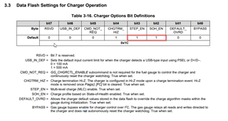
    There is a bit called CMD_NOT_REQ. If this bit is left to 0 i have to use the command GG_CHGRCTL_ENABLE to enable the control of the charger through the gasgauge. But if i set to 1 how to control the charger? Directly through the Charger I2C Interface or with BYPASS=1 through the I2C Interface of the gauge?

    If SOH_EN=1 the charge profile is based on State-of-Health. Can you explain me what exactly this means?

    Nice weekend.

    Regards,

    Alex

  • Hi Alex,

    Regarding CMD_NOT_REQ = 1, the gauge will control the charger as the host, the same way it would if the GG_CHGRCTL_ENABLE command is sent with the communication happening between the gauge and charger I2C interface. If BYPASS = 1, then I believe that charger commands can be sent to the charger from the host with being relayed by the gauge.

    Below has a deeper explanation of what enabling SOH_EN = 1 does for the charge profile:


    Regards,

    Anthony Baldino

  • Hi Anthony,

    I've set both SOH_EN=1 and STEP_EN =1 to achieve a better SOC prediction during the lifetime of the battery. It's make sense? In my old settings both were set to 0.

    What exactly is the meaning of the bit DEFAULT_OVRD and what should I understand under "Override the charge algorithm masks within the gauge during initialization"? Initialization it means after RESET and/or something else?

    I'm in doubt with the settings regarding the "Load Mode". I'm not sure if my application is more constant power or constant current. When i look from the battery side, my opinion is that i have constant power, because how voltage decrease, the current will increase during the operation. What exactly describe best a constant current load?

    I observed in the past with the old golden image that the displayed value of the SOC differs till 6-7% when i power on the device. Could be the reason for that the wrong value for the "Load Select"? It was set Load Mode = 0 and Load Select = 1. Now i would like to change Load Mode = 1 and Load Select = 3. It's make sense?

    Thanks in advance for your help.

    Regards,

    Alex

  • If SOH_EN=1 and STEP_EN=1 than the charging current will go beyond the current set by the temperature profile. It's correct?

  • Hi Alex,

    I've set both SOH_EN=1 and STEP_EN =1 to achieve a better SOC prediction during the lifetime of the battery. It's make sense? In my old settings both were set to 0.

    Yes, this makes sense. Typically the default value for both SOH_EN and STEP_EN are 1:

    What exactly is the meaning of the bit DEFAULT_OVRD and what should I understand under "Override the charge algorithm masks within the gauge during initialization"? Initialization it means after RESET and/or something else?

    Regarding DEFAULT_OVRD, this allows for the default values within the charger to override the charge algorithm of the gauge upon the initialization of communication, whether that be by command reset or power on reset. I believe this setting would be for an application where the standard charge profile of the charger is preferred to that of the gauge where certain other aspects such as SOH are taken into account of the charge profile.

    I'm in doubt with the settings regarding the "Load Mode". I'm not sure if my application is more constant power or constant current. When i look from the battery side, my opinion is that i have constant power, because how voltage decrease, the current will increase during the operation. What exactly describe best a constant current load?

    Regarding Load Mode and Load Select, can you please go more in depth about the load profile to give us a better idea of what the settings should be?

    I observed in the past with the old golden image that the displayed value of the SOC differs till 6-7% when i power on the device. Could be the reason for that the wrong value for the "Load Select"? It was set Load Mode = 0 and Load Select = 1. Now i would like to change Load Mode = 1 and Load Select = 3. It's make sense?

    This could be causing this issue, we will have a better idea once we know what the load profile is of this application.

    If SOH_EN=1 and STEP_EN=1 than the charging current will go beyond the current set by the temperature profile. It's correct?

    I believe in certain situations this is correct. STEP_EN enables the multi-level charging algorithm that is based on the temperature profile inputted in the data flash, and SOH_EN will either increase or decrease the current based on the SOH of the cell.

    Regards,

    Anthony Baldino

  • Hi Anthony,

    thank you for your valuable response.

    The charger and gasgauge is part of a medical monitoring device. The device will be used mostly with an external power adapter (so the battery is for the most time fully charged). During transportation (or other things) the device will be powered from the battery. 

    Our device has an averrage current consumption from battery of approx. 300-350 mA.  The current is not constant over time. It show peaks for short time caused by the wifi/bt module, eMMC, microcontrollers, sensors etc. The battery has a capacity of 4400 mAh.

    Regards,

    Alex

  • Hi Alex,

    If possible, would you happen to have a high sampled load profile data on this device? This will give us a better idea of which settings to select.

    Also, Section 2 of this document below has more information on each of the Load Mode and Load Select options:

    http://www.ti.com/lit/pdf/slua948 

    Regards,

    Anthony Baldino

  • Hi Anthony,

    i suppose you mean a .log file logged by bqstudio? At the moment i not have such a file. I will try, if needed, to generate it with the old golden image.

    However, i've read the document you mentioned in your previous answer and i think the Load Mode has to be set for my application to "Constant power" because the current is changing as battery voltage change. What is your opinion?

    For Load Select, i'm not sure which is the best setting. The Load is not changing to much between discharge cycles. Only if i switch the wifi/bt module the load will increase about 10-15%. Do you think I can use the setting "Average discharge load from the previous discharge cycle", so value 0 and not 3 or you have another proposal?

    Regards,

    Alex

  • Hi Alex,

    A .log file from bqStudio could work, we just need more data on how the load uses voltage and current over time, and to get a better idea of how the current spikes from time to time. 

    Regarding the usage of Constant Power, this could work since there are changes occurring to the current and is not constant at all times. In regards to the load select, this is where we would need to look at the load profile to get a better idea of what to chose for this option.

    Regards,

    Anthony Baldino

  • Hi Anthony,

    I was able to perform a new learning cycle and as a result I create a new golden image (after doing also the calibration steps).

    Now I try to find out which Load Mode / Select fit best my application.

    BQStudio offer a view for the passed charge and a bit WAIT_ID in Flags().

    First, what is the meaning of the WAIT_ID Bit and where (from which register) should i take the information about the passed charge.

    Regards,

    Alexandru

  • Hi Alex,

    WAIT_ID is set when the gauge is waiting to identify an inserted battery.

    Regarding how to take the information of the passed charge, this can be quantified in the .log file where the measurements taken will be labelled as Qpass.

    Below is more information on how Passed Charge is measured:

    https://e2echina.ti.com/cfs-file/__key/telligent-evolution-components-attachments/00-24-00-00-00-00-02-91/Theory-and-Implementation-of-Impedance-Track-Battery-Fuel_2D00_Gauging-Algorithm.pdf 

    Regards,

    Anthony Baldino

  • Hi Anthony,

    if the WAIT_ID will remain set  (after a long time a battery was inserted) what is the meaning of this? In other words when it will be set respectively cleared?

    I want to implement the function Passed Charge() in our embedded device. How BQStudio does this calculations?

    Regards,

    Alexandru Mixich

  • Hi,

    due to some safety issues, the battery cell manufacturer recommand to charge with 4.1V instead with 4.2V. I've set as a value for "Terminate Voltage" resp. "Final Voltage" 3000mV. Should I change now to 2900 mV to allow more passing charge? Or should i set to a higher value?

    Regards,

    Alex

  • Hi Alex,

    if the WAIT_ID will remain set  (after a long time a battery was inserted) what is the meaning of this? In other words when it will be set respectively cleared?

    Can you tell me if the BAT_DET bit is also set during this time? Also, can you please tell me what value of pull up resistor you have on the BI pin of the device?

    I want to implement the function Passed Charge() in our embedded device. How BQStudio does this calculations?

    If you are implementing a PassedCharge() function, this can be done by reading out from 0x68 and 0x69 of the gauge.

    due to some safety issues, the battery cell manufacturer recommand to charge with 4.1V instead with 4.2V. I've set as a value for "Terminate Voltage" resp. "Final Voltage" 3000mV. Should I change now to 2900 mV to allow more passing charge? Or should i set to a higher value?

    This depends on the respective ChemID is being used for this application. Can you please tell me which ChemID is being used?

    Regards,

    Anthony Baldino

  • Hi Anthony,

    yes, the BAT_DET Bit is set all the time. The WAIT_ID is not set all the time. I'm not sure which event was responsible to set respectively to clear it. Maybe it was set when i've disconnected the battery for a short time. I'm not sure.

    The BI Pin has 1.8M as a pull up as you can see in the picture below.

    We use in our project the ChemID 0x2043. We use 2 cells connected in parallel.

    I made some tests to find the right combination for Load Mode / Select settings and observed due to lower charging voltage used that the FullAvailable Capacity value reaches 3400mAh. Because I've set for the DesignCapacity the value 4400mAh, the SOH value is set to about 78%. We allow in our embedded device only values higher than 82%.

    So should i use for design capacity the value of 3400mAh? I think maybe is better to do a new learn cycle with the reduced charging voltage of 4.1V and new design capacity. What is your opinion?

    Regards,

    Alex

  • Hi Alex,

    I believe that both of these issues could be rooting from the same area, which could be the chemID. I would not lower the design capacity from the original 4400mAh.

    Can you please tell me how the chemID was chosen for this device? Was the GPCCHEM tool used to find this match?

    Also, can you please tell me if this ChemID is set for both the OCVa0 and OCVa1 Table ChemID's in bqStudio?

    Regards,

    Anthony Baldino

  • Hi Anthony, 

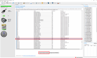
    you were right. I make a wrong selection of the chemical ID. It was the standard 0x1202. I forgot that i need to programm it through BQStudio to change it on bq27531.

    Please confirm from the attached datasheet and the picture below that my selection now is correct.

    2021-11-01-V01_DB.PA-L2238.K01.R001.pdf

    I will start now a new learn cycle with 4.2V charging voltage. Correct?

    Regards,

    Alex

  • But I'm still confused with SOH.

    When I will use 4.1V as a charge voltage, the FCC value will be clearly less as Design Capacity value. So the SOH value will be less then 80%. 

    How to deal with this issue?

  • Hi Alex,

    Before starting the learning cycle with the new ChemID, please use the GPCCHEM tool below to ensure that it is the best match for the cell you are using. There are occasionally inconsistencies with the naming and use case that the ChemID was created in, and the usage of this tool will allow us to confirm that it is the best match possible.

    https://www.ti.com/tool/GPCCHEM 

    I believe that the previous issue with the low FCC value compared to the Design Capacity could of been caused by the wrong ChemID issue. If this issue is still apparent during after the new chemID is implemented, we can look into the parameters. For this learning cycle however, please keep the design capacity the rated value for the cell for the most accurate learning possible.

    Regards,

    Anthony Baldino

  • Hi Anthony,

    ok, i will use the GPCCHEM tool to find the most suitable ChemID.

    But our battery pack has 2 cells in parallel. Will GPCCHEM take this in account? All the TI ChemIDs characterize only 1 cell.

    In the configuration file i have only the possibility to specify the number of cells in series. I assume in this case in my case i have to put 1. Correct?

    Regards,

    Alexandru Mixich

  • A notice. Our battery pack has implemented a safety circuitry which add an additional resistance. It will this be considered by the GPCCHEM?

  • Hi Alexandru,

    You are correct about putting 1 for the number of cells, however when completing the measurements for the GPCCHEM tool, please leave the two cells connected in parallel.

    Regarding the safety circuitry, is it possible for this to be disabled or removed for testing? This could possibly affect the chemID match for the cell due to the additional resistance.

    Regards,

    Anthony Baldino 

  • Hi Anthony,

    no is not possible to disable the safety circuitry for testing. 

    However i talk with the baterry pack manufacturer an he suggested me to use the ChemID  2154. 

    I will run now a new learn cycle with this ChemID.

    Regarding SOH calculation I still have a doubt.

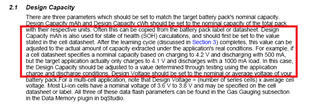
    In the document SLUA903 it stays in case using a lower charging voltage (i.e 4.1V) to adjust the Design Capacity accordingly.

    So the learn cycle will be with executed with 4.2V and a Design Capacity of 4400 mAh. For the usage in the field i will use 4.1V as a charging voltage.

    Through a Charging/discharging phase i will determine how much Passed Charge was crossed and take this value as a new design capacity.

    Could be this a practical way to overcome the issue with SOH calculation?

    Regards,

    Alex

  • Hi Alex,

    For the learning cycle, please keep the design capacity and charge voltage to the stated value (4400 mAh and 4.2V), and then after the cycle is completed the design capacity and charge voltage can be changed as long as they are being reduced from the learning cycle values.

    This will allow for the gauge to learn the maximum potential of the cell for when the Ra Table and Qmax values are created.

    If this does not correct the SOH calculation issue, we can look into other parameters that could alleviate the issue.

    Regards,

    Anthony Baldino

  • Hi Anthony,

    I've performed the lerning cycle with the stated values (4400mAh and 4.2V) and changed those to the desired ones (3900mAh and 4.1V). I set the Load Mode to 1 (constant power) and Load Select to 1 (Present average discharge power). I will test also other Load Select  possibilities to find the optimal settings for our application.

    However the first tests shows a good tracking of the remaining capacity but I'm not able to read the passed charge through 0x68 and 0x69. I read it as Standard Command in NORMAL operation mode. Is this correct or do you suggest another way to access the PassedCharge information?

    Regards,

    Alexandru Mixich

  • Hi Alexandru,

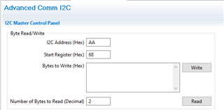
    Please try reading the Passed Charge via the Advanced Comm I2C panel in bqStudio, while having the I2C Address as AA and Start Register at 68.

    Please let me know if this allows you to read the passed charge.

    Regards,

    Anthony Baldino

  • Hi Anthony,

    we've successufully implemented the read function of the PassedCharge. The read implementation in our software was wrong.

    However in the meantime i've made some tests after the learn cycle with different values for DesignCapacity, Qmax0 and Qmax1.

    But i was faced with a strange behaviour.

    1. Because i charge with 4.1V instead 4.2V i observed that the max. capacity what can be achieved was around 4000 mAh, so approx. 10% less as the capacity reached during the learn cycle. So I changed the design capacity to 3900mAh, the CC Threshold to 3500mAh and Qmax Cell 0 (DF GG Class) to 3900 mAh. I monitored the passed charge during a full charging and the value has matched more or less to the new design capacity. But the value for Full Charge Capacity was updated to around 3300mAh.

    2. I changed the value for design capacity and Qmax Cell 0 to 4400 mAh (the original one). The value for Full Charge Capacity was updated to around 3700mAh

    3. I changed the value for design capacity and Qmax Cell 0 to 4500 mAh (the original one). The value for Full Charge Capacity was updated to around 3900mAh

    In all 3 cases i charged and discharged the battery but the SOH was set to 87% and the SOH state just to 0x02. The battery used for the tests is new. Normally the SOH state should be 0x03. Correct?

    As i mentioned in my early posts, our battery pack has a sefety circuit which increase the battery resistance seen by the gauge with approx. 100mOhm.

    Cold be the additional impedance the reason for our strange behaviour? If yes, how the additional resistance can be compensated in the calculations done by the gauge? Should not do this the Learn Cycle?

    Regards,

    Alexandru Mixich

  • Hi Alexandru,

    1. Because i charge with 4.1V instead 4.2V i observed that the max. capacity what can be achieved was around 4000 mAh, so approx. 10% less as the capacity reached during the learn cycle. So I changed the design capacity to 3900mAh, the CC Threshold to 3500mAh and Qmax Cell 0 (DF GG Class) to 3900 mAh. I monitored the passed charge during a full charging and the value has matched more or less to the new design capacity. But the value for Full Charge Capacity was updated to around 3300mAh.

    2. I changed the value for design capacity and Qmax Cell 0 to 4400 mAh (the original one). The value for Full Charge Capacity was updated to around 3700mAh

    Regarding both of these situations, is it possible to receive a .gg and log file for both? This will allow us to look deeper into what could be causing this difference in FCC.

    3. I changed the value for design capacity and Qmax Cell 0 to 4500 mAh (the original one). The value for Full Charge Capacity was updated to around 3900mAh

    I believe you stated before that the learning cycle was done with a design capacity of 4400 mAh. We would not recommend changing the design capacity to a value higher than the value the learning cycle was done with. 

    Regards,

    Anthony Baldino

  • Hi Anthony,

    the distributor of the battery pack has informed me that the capacity is really 4500mAh. So the Learn Cycle was performed with this capacity. You were right when you afirmed NOT to change the design capacity to a lower value as it was used during the learn cycle. All the calculations in a gas gauge will go in a wrong direction otherwise.

    I changed the design capacity and Qmax Cell 0 to 4500 mAh. Now the Full Charge Capacity was updated after 1 cycle to 4040 mAh which i think represent a good value when using 4.1V as a charging voltage.

    The value of SOH is around 90 - 93% which i think is also OK. We will use this value as a 100% in our application. However the SOH status on one device shows 0x02 and on a second 0x03. As i understood the value 0x03 represent a SOH calculation based on a compensated Qmax and 0x02 on a uncompensated Qmax.

    Can you tell me please at which time or what will influence the status to change from 0x02 to 0x03. 

    At Charger Control Configuration there is a value to be set named Charge Disabled Regulation Voltage. The explanation in technical manual says that this is the regulation voltage the charger is configured to when the battery is not beeing charged. At the moment this is set to 4200mV. I should leave it at this value or should i adjust it for example to 4150mV, because the max. charging voltage is 4100mV in our application?

    Regards,

    Alexandru Mixich

  • Hi Alexandru,

    Can you tell me please at which time or what will influence the status to change from 0x02 to 0x03. 

    I believe that the difference between the 0x02 and 0x03 values reported by the SOH Status are representative of the when the Qmax taken for the calculation of the SOH calculation is taken. The Qmax used for the SOH when at 0x02 is the initial value after the cell has been inserted, and 0x03 is after a charge and relax has been preformed and Qmax has been updated.

    At Charger Control Configuration there is a value to be set named Charge Disabled Regulation Voltage. The explanation in technical manual says that this is the regulation voltage the charger is configured to when the battery is not beeing charged. At the moment this is set to 4200mV. I should leave it at this value or should i adjust it for example to 4150mV, because the max. charging voltage is 4100mV in our application?

    I believe that since this value is when the battery is not being charged, it should be set to what the max. charging voltage is.

    Regards,

    Anthony Baldino

  • Hi Anthony,

    thanks for your valuable Informations. I really appreciate your support.

    In the meantime also the device whith 0x02 now changed to 0x03. So the relax time after charging was necessary to update. 

    During my tests i observed that the value for the FullChargeCapacity changes with discharge / charge phase. I discharge every time till the Battery voltage fall below slightly the Final Voltage (in my case 3000 mV) and i charge with 4.1V until the Taper current is reached (in my case 130 mA).The FullChargeCapacity value is lower at the end of the discharge phase as when is full charged.

    The second observation i made is that at the second discharge / charge cycle the reported FullChargeCapacity has increased over 10% at the end of charging.

    Do you have an explanation for this 2 observations?

    Regards,

    Alexandru Mixich

  • Hi Alexandru,

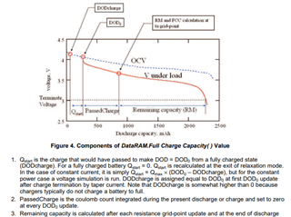
    Below is how the Full Charge Capacity is calculated and when this value is calculated within the gauge. This could also be occurring since the gauge is learning more about the FCC and other values each time a cycle occurs.

    This information can be found here: https://e2echina.ti.com/cfs-file/__key/telligent-evolution-components-attachments/00-24-00-00-00-00-02-91/Theory-and-Implementation-of-Impedance-Track-Battery-Fuel_2D00_Gauging-Algorithm.pdf 

    If possible, please send a log file of this occurrence and we can look more into it.

    Regards,

    Anthony Baldino

  • Hi Anthony,

    at the moment I can't deliver you a log file. To do this i have to change something on our PCB board and software to go through BQStudio log mechanism. We work now to a sollution to log the gasgauge data through our device software.

    At the moment i have more relevant issues which need to be solved.

    1. The SOC was set to 0% although the Batt. voltage was above the TerminateVoltage Level.  In our case the TerminateVoltage was set to 3000mV.

    In the SLUUA96A document stays

    In my case it seems that not only the Terminate Voltage influence the SOC to be set to 0. Do you have any idea what else could be the cause?

    2. Sometimes when the Taper Current is reached the SOC is not changing to 100%. It shows 97, 98 or 99%. I've set the Taper current  to 130mA and the Taper Voltage to 100mV. Do you know the reason for this?

    3. Which settings i have to change when a battery will be exchanged in the system? It's enough to set the Cycle Count 0 to 0 and Qmax Cell 0 to DesignCapacity value? Or anything else to?

    Regards,

    Alexandru Mixich

  • Hi Alexandru,

    Regarding #1 and #2, it is difficult to point to a root cause of both of these issues without a .log file since it allows us to see within all of the registers of the gauge. Please send one once it is able to be created.

    1. Can you please tell me what the Reserve Capacity is? I would need more data to look into the cause of this.

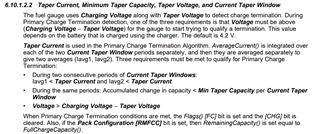
    2. I believe that with certain settings the SOC will only move to 100% once the FC flag has been set. Please ensure that all of these conditions below are being met to set FC:

    3. I believe you are correct, I will get outside council for confirmation.

    Regards,

    Anthony Baldino

  • Hi Anthony,

    Regarding #1, the setting for the ReserveCapacity is set to 0.

    At #2 i changed the TaperVoltage from 100mV to 70mV and the TaperCurrent from 120 to 150mA and it seems now to work better. The SOC of 100% will be achieved. By the way, the FC Bit was set all the time. But i'm NOT understand how a smaler value of TaperVoltage influence so much the SOC accuracy.

    At #3 just confirm. For me it's look to be the right way.

    Regards,

    Alexandru Mixich

  • Hi Alexandru,

    Thank you for clarifying, regarding #1 and #2, please let me know when a .log file is created for this situation. This will give us a better look into what this root cause is. The reduction in Taper Voltage could have caused a quicker path to the clearing of the voltage condition for charge termination, which could of helped the SOC.

    If the same cell is being used to swap in, then I believe that these are the only parameters needed to be changed. The measurements might slightly be off for the first couple cycles, but this should just be the gauge learning the cell.

    Regards,

    Anthony Baldino

  • Hi Anthony,

    thanks for your reply. I will try in the next time to send you some logs.

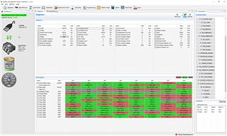
    I have a new issue. Now regarding the Precharge process. When reading the Reg03 of the charger register through bqstudio the setting show me that the value set corespond to a precharge current of 128 mA. But the average current shows twice the value (see the picture below). The transition of precharge to fast charging is set to 3.0V in Reg04.

    I discharged the battery to around 2.8V. Is this behaviour correct?

    Regards,

    Alexandru

  • Hi Alexandru,

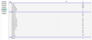
    Can you please confirm if any calibration has been done to this gauge regarding the current measurements? If you are not able to pull the .gg file of the gauge, can you please tell me what these values are set to in your data flash?

    Can you also tell me what value of sense resistor is being used?

    Also if possible, can you please attempt putting a 128mA across the sense resistor to confirm this is the value being seen in bqStudio? This will allow us to determine whether this is a configuration or calibration issue.

    Regards,

    Anthony Baldino

  • Hi Anthony,

    yes the calibration regarding the current measurement was done.

    Attached you can find the .gg file.

    GG_VG5_1003.gg.csv

    The sense resistor used is 10mOhm.

    I will do the test suggested by you tomorow.

    Regards,

    Alexandru Mixich

  • Hi Alexandru,

    Thank you for sharing the .gg file.

    Please let me know the results of the test when completed.

    Regards,

    Anthony Baldino

  • Hi Anthony,

    i took the current measurement and it seems to be very accurate.

    So i have no explanation why i saw twice the precharge current.

    But in the mean time a new old problem have occured.

    I wrote some posts ago that the charging was finnished (FC was set) with SOC being at 96%-97%. As i conclusion i changed the Taper Voltage from 100mV to 70 mV and the TaperCurrent from 130mA to 150mA.

    But now the opposite occurs.

    The SOC is set to 100% without FC to be set. The AverageCurrent of 273mA is bigger as the TaperCurrent (set to 150mA)

    What could be the cause for this behaviour now?

    Regards,

    Alexandru Mixich

  • It's maybe possible to do a Webmeeting (over Teams)?

    Regards,

    Alex

  • Hi Alexandru,

    Based on that image, the process that SOC is measured is Remaining Capacity / Full Charge Capacity. Using the values in that image, the SOC would be 99.6%. However, there could be conditions in the Primary Charge Termination that are still not being met that would set the FC bit.

    Regarding a meeting, I would prefer waiting until we get a log file containing the issue, since we will not truly be able to discover the root cause of the issue without one even if we hold a meeting.

    Regards,

    Anthony Baldino

  • Hi Anthony,

    i meant a meeting to discuss about some topics regarding gas gauging not specially for an issue. However if it's not possible than we will wait first the logging.

     I have a further question. In DF there is a parameter called "Min. Taper Capacity" and "Current Taper Window".  They have been set with 25mAh and 40s. What do you think, should i change one of them and see what's happen? Or to let them as they are?

    Regards,

    Alexandru Mixich

  • Hi Anthony,

    From what I've read I understood that the charger has a safety timer to prevent extended charging cycle due to abnormal battery conditions. 

    In Reg5 i enabled it (seting Bit3) and set the time for 8 hrs (Bit2=0 and Bit1=1). As test equipment i used a battery simulator where i set a static SOC of 30%. That means the simulator held this State of Charge how long its needed. 

    After running more than 24 hours, the expiration of the timer was NOT detected in Reg9 (the Bits CHRG_FAULT[1] and [0] has been not set to 11 = Charge time expiration).

    The configuration is the same as a sent it you in my previous post GG_VG5_1003.gg.csv

    Do you have any idea why this happen? How can i check that the timer has been started?

    Regards,

    Alexandru Mixich

  • Hi Alexandru,

    Sorry for the delay, you could change the Current Taper Window to see if this will help the gauge reach Charge Termination. The Current Taper Window is the amount of time the 2 consecutive windows must meet the conditions, so lowering this could help this issue.

    Regarding Min Taper Capacity, I do not think this value should change more than it is already set, since this is based on the passed charge during these windows.

    Regarding the timer issue, please let me look into this and report my findings.

    Regards,

    Anthony Baldino

  • Hi Anthony,

    i changed today the safety timer to 5 hrs and reduced the charge current but still it has been not expired, after 9 hrs of charging.

    Do i test correctly?

    Regards,

    Alexandru Mixich