This thread has been locked.

If you have a related question, please click the "Ask a related question" button in the top right corner. The newly created question will be automatically linked to this question.

BQ24618: Reliability improvements

Part Number: BQ24618

Hello,

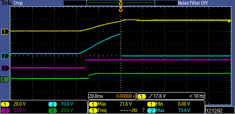
We are using the BQ24618 for a 4S charging application. The product has been on the market for some time now and we have not had any major issues with the design. In rare cases however, we have had some chargers whose BQ chip has failed after very little use.

As we are planning to incorporate the charger into a future product, any feedback on how the reliability of the current design can be improved is appreciated.

I am attaching the schematic and layout design.

Thank you!

Boris Yanchev

Blueye Charger.pdf

  • Hi Boris, 

    Thank you for reaching out!

    Could you please elaborate on the observed behavior? 

    Best Regards, 

    Aya Khedr 

  • Hi Aya,

    Thank you for your reply.

    With reference to the schematic, TP3 (VBUS), TP2 (ADAPTER+) and the load side of R2 all measure 20.2V, which means that PD is correctly negotiated. TP1(CHG_OUT) however measures 4.9V, instead of the expected 16.8V. There is no sign of any mechanical damage to the PCB itself, nor any hot spots (the BQ IC measures around 60C). Also, the STAT LEDs show charging in progress even though no battery is connected.

    I hope this helps.

    Kind regards,

    Boris

  • Hi Boris, 

    Thank you for the clarification. 

    I reviewed the schematic provided and have a couple comments below: 

    1- The best stability occurs when the LC resonant frequency is within the range of 12kHz-17kHz for the BQ24618. 

    2- For charge current = 4A, the typical inductor value is 6.8uH and the typical output capacitance is 20uF (see below)

    I would like to further identify why the battery voltage is 4.9V instead of the expected 16.8V.

    Could you please provide a scope capture upon power up similar to the waveform below?


    Best Regards, 

    Aya Khedr 

  • Hi Aya,

    Thank you for looking into this.

    I am actually working remote this week and do not have access to the hardware, so I will get back to you mid next week.

    Regards,

    Boris

  • Hi Boris, 

    Thank you for the update. 

    I look forward to hearing back from you soon. 

    Best Regards, 

    Aya Khedr 

  • Hi Aya,

    The battery voltage is 4.9V on the unit that failed, working units have the correct voltage.

    Here is the scope capture you requested of a working unit.

    (1 Vcc, 2 /PG, 3 Vref, 4 REGN)

    Kind regards,

    Boris

  • Hi Boris, 

    Thank you for capturing. I would be interested to see this waveform on a failed unit if possible. 

    Best Regards, 

    Aya Khedr 

  • Hi Aya,

    Here is a capture of a failed unit. The battery voltage is 4.9V and the status LEDs show charging even though no battery is connected.

    Kind regards,

    Boris

  • Hi Boris, 

    Are you testing these units with the battery disconnected or connected?

    Could you also do an ABA swap by placing a working unit onto the board that is not working?

    Best Regards, 

    Aya Khedr 

  • Hi Aya,

    The tests so far have been done without a battery connected.

    Replacing the broken IC fixes the issue and the battery charges as normal.

    Kind regards,

    Boris

  • Hi Boris, 

    The battery charger's typical charging profile assumes a battery is connected. 

    Please let me know if you have additional questions. 

    Best Regards, 

    Aya Khedr

  • Hi Aya,

    Thank you for your reply, although I do not understand how it explains the failures.

    Is a unit more likely to fail if not connected to a battery when powered on?

    Regards,
    Boris

  • Hi Boris, 

    After doing more analysis on the waveform above, it looks like the REGN voltage on the failed unit is higher than we expect (circled in red).

    This voltage should be regulated at ~6V (similar to what is seen in the normal waveform).

    It seems that there may be damage to the REGN pin which would then cause the battery output voltage to be incorrect. Unfortunately, I am unable to definitively say why REGN voltage is abnormal without knowing what caused this.  

    Best Regards, 

    Aya Khedr