This thread has been locked.

If you have a related question, please click the "Ask a related question" button in the top right corner. The newly created question will be automatically linked to this question.

LMR43610-Q1: Large amount of failures

Part Number: LMR43610-Q1

Hi,

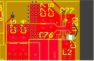
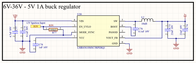
I have a LMR43610MSC5RPERQ1 on my PCB and am experience a near 100% failure rate at random times. There is nothing notable happening when they get damaged, they just suddenly get hot and pop out of nowhere (With visible marks left).

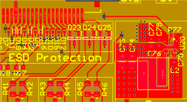
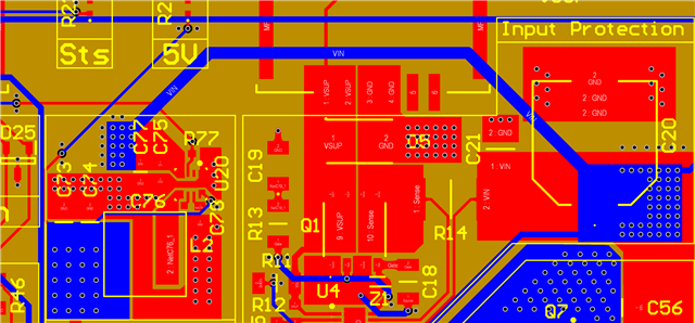
Here is my schematic, I don't understand what could be happening. supply voltage is coming through a protection circuit before reaching this device. Enable signal is coming from an off board ignition switch.

Thank you!

  • Hello

    Is it possible to monitor the VIN, EN, SW, and 5Vout and wait for a failure.

    That will give us some data to work with.

    Does the failure occur during power up ?  Or IGN start ?

    Can you provide images of your PCB layout.

    Thanks

  • Unfortunately this happens at completely random points, for example the device was running for 12 hours recenetly with no issues so it would be hard to monitor for faults.

    Here is how the part is on my layout:

    Enable and VIN are at 24V

  • Hello

    The only issue I see is with the grounding of C78.  

    It should be grounded closer to the regulator ground.

    I have attached an example.  You may be able to hack that

    in on a board with copper tape and test it out.

    I understand that it may take a while to get waveforms, but I think it is the

    most direct route to finding out what is going on.

    It looks like the VIN and EN nodes are separated on the schematic ?

    Are those independent signals ?  If so, what is the power sequence ?

    Do you have an input filter to VIN or IGN ?  Is the filter damped ?

    Thanks

  • Ok, Ill will monitor these as see if I get anything that looks like it can cause damage or wear the device down.

    VIN and EN are powered at the same time from the same source but through different wires.

    There is a protection circuit before VIN that removes anthing outside of 6-36V. No filter on IGN, maybe that is the issue? What filter would you usually suggest in this use case? Maybe for this design I can short IGN to VIN (And remove IGN external wire) as it is coming from the same source anyway?

    Thanks!

  • Hello

    I think it is a good idea to connect VIN and EN.  That way they will both have filtering.

    You might be able to hack that in, along with the VCC capacitor edit, and test.

    Thanks

  • Hello

    I will close this post due to inactivity.

    You can re-open if you need more help.

    Thanks