Other Parts Discussed in Thread: TL494
Hi, good day.
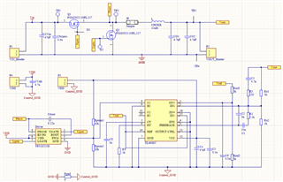
I'm a college student. When i research for a synchronize BUCK converter, the problem, the two Ugate and Lgate outputs signal of TPS28225 is LOW but the PWM pin is high signal.
In this condition is, when I test Open Loop function of a synchronize BUCK converter. First, I removed the PWM IC and used a signal generator to provide pulse wave to the PWM pin of TPS28225, the gate driver and the waveforms is correct, I think. (Figure. 1.) (Spec. of Buck: Vin=24V, Vo=5V, fsw=200khz, Load,max=1A, G.D. VDD=6V)
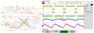 Figure. 1. Open Loop Test Condition.
Second, I connected the PWM IC(TL494), provide PWM signal to TPS28225 PWM pin. the PWM IC output was HIGH but the outputs signal of TPS28225 is LOW, that mean the high side MOS can't been driven, so the up side MOS always turn off (Vds,Q1=Vin) and output voltage is 0.
I don't know why I just changed the PWM signal source from signal generator to PWM IC, but the outputs signal of TPS28225 is not the same between the two conditions.(Figure. 2.)
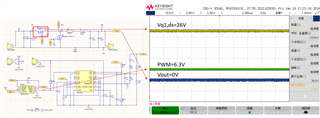 Figure. 2. Close Loop Test Condition
Please provide some suggests for me, so appreciate.

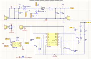
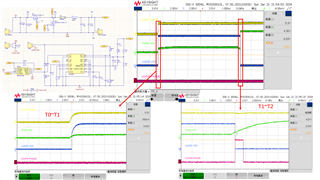 Figure. 1.