[FAQ] Can TI's non-isolated half bridge drivers be used in 100% duty cycle applications?
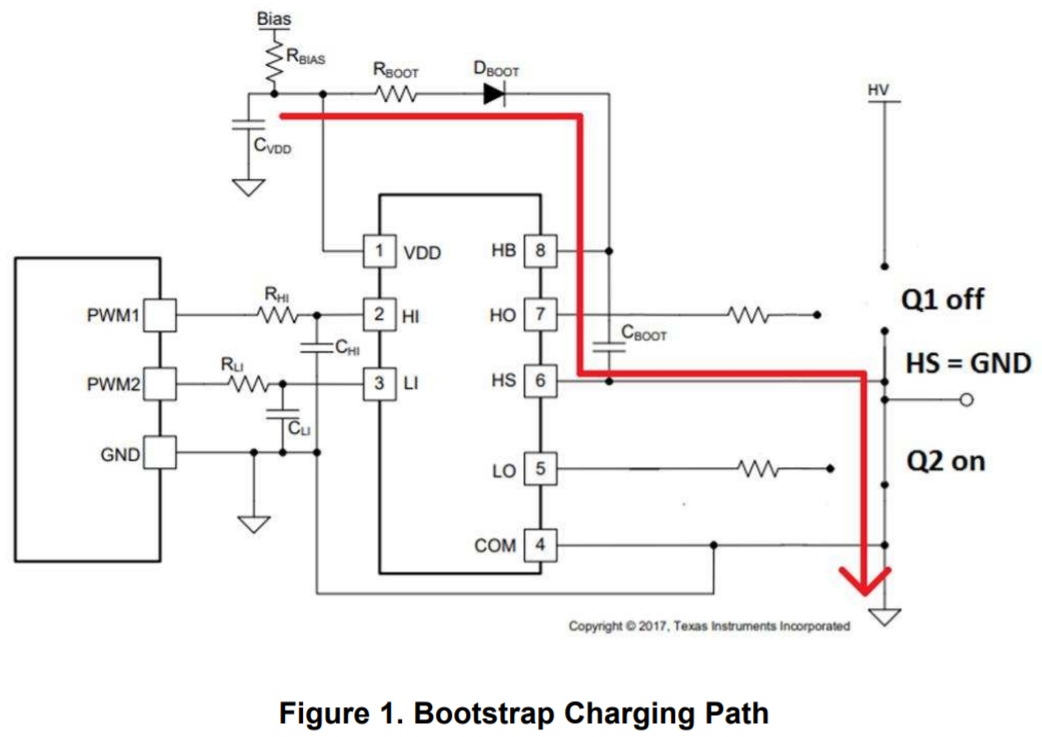
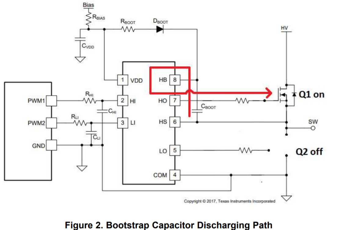
TI’s non-isolated half bridge drivers do not internally generate the bias for the high side channel. Instead, they use an external bootstrap circuit to keep the high side biased. However, the bootstrap circuit cannot provide bias to the high-side channel when using 100% duty cycle, since it relies on the switching of the high side and low side FETs in order to charge the bootstrap capacitor to keep the high side biased: the capacitor CBOOT recharges when the high side FET is OFF and the low side FET is ON (Figure 1) and then it will discharge when the high side FET is ON and the low side FET is OFF (Figure 2). For details about the bootstrap circuit please refer to this application note: https://www.ti.com/lit/pdf/slua887


To achieve 100% duty cycle on the high side driver, there needs to be a constant bias on the high-side HB-HS pins to maintain the high-side floating supply above the HB-HS UVLO of the driver:
- One way to achieve 100% duty cycle is to use an isolated floating power supply from HB to HS to provide the supply for the high side. This floating supply needs to be isolated since the switch node HS is switching from GND (when high side gate is OFF and low side gate is ON) to Vbus (when the high side gate is ON and the low side gate is OFF). Another consideration is to make sure not to exceed the operating conditions of the HB-HS voltage of the driver.
- Another way of creating 100% duty cycle is to use the low side channel to generate an oscillator that charges a HB-HS charge pump. One key consideration about this solution is that the low side driver is being used as part of the charge pump circuit and therefore cannot be used to drive a low side FET on a half bridge configuration. Another important consideration with this solution is that it is not suitable for high switching frequency, since the charge pump capacitor is a fairly large value and is connected to the switch node. This application note describes this solution in detail: https://www.ti.com/lit/pdf/sluaa58

