Other Parts Discussed in Thread: , TPS25990
Hello,
I have a custom board design using 3x TPS25985 chips (one primary and two secondary). The eFuses are used to prevent voltage being applied to a high-current part of our board until other initialization operations occur; the eFuses are enabled using GPIO from embedded software. The eFuses are designed to support up to 135A with a input voltage of nominally 12-16V.
The issue we're facing is that as soon as we enable the eFuses, they shutoff within about 175ms. I'm having a terrible time trying to find the root cause of our issue.
Currently, I'm bypassing the normal load of our circuit and wiring the output of the eFuses to an electronic load. My input voltage is set to 15V and the electronic load is set to pull 10A constant current. I've collected oscilloscope traces of as many pins as possible. Hopefully someone has ideas?
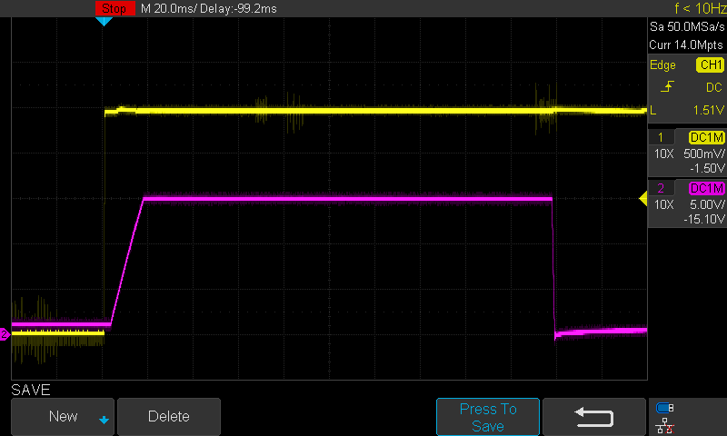
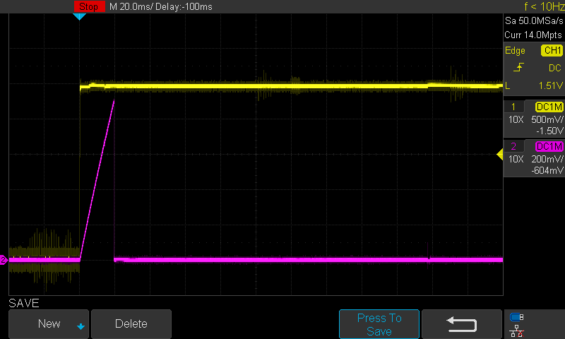
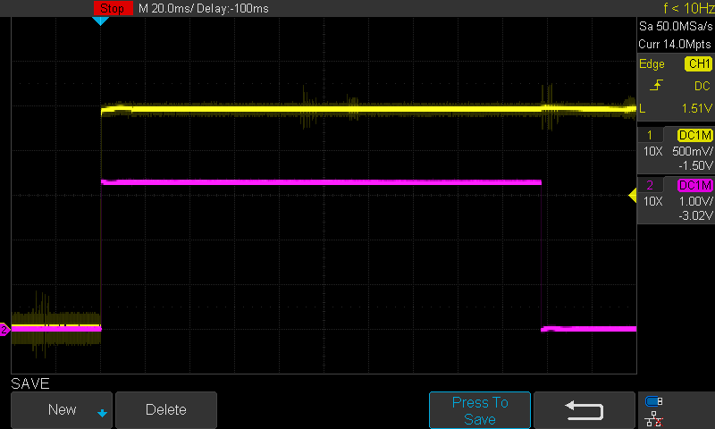
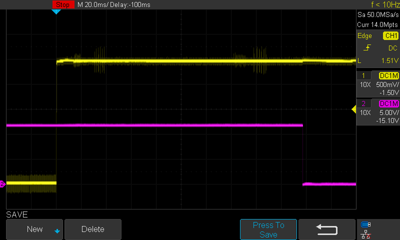
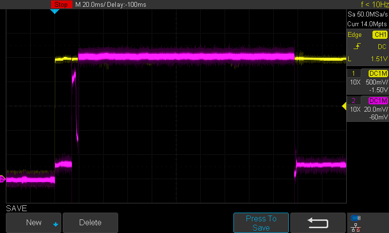
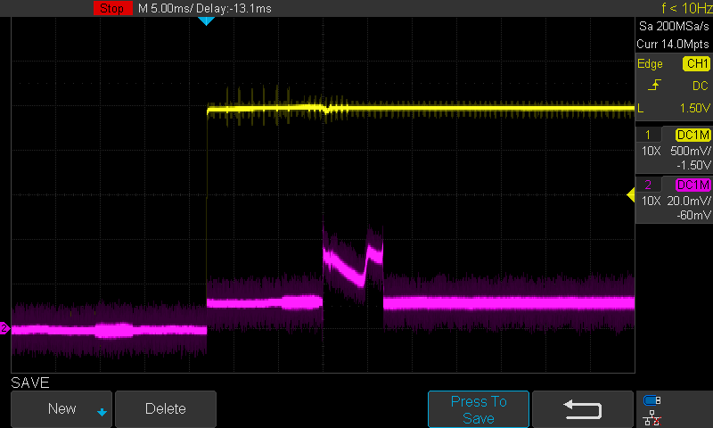
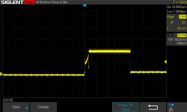
The most interesting plot I believe is of the ILIM pin. On the primary eFuse, at startup there appears to be some interesting behavior that (a ramp, followed by a strong ringing pulse, followed by a slow ramp, then drop, then finally leveling off to a constant voltage). Based on my RILIM of 560ohms, the steady-state value of ILIM appears to indicate that a full 10A is making it through the primary eFuse before it shuts off. Below are three plots of voltage at ILIM at three different zoom levels.
50ms/div:
2ms/div: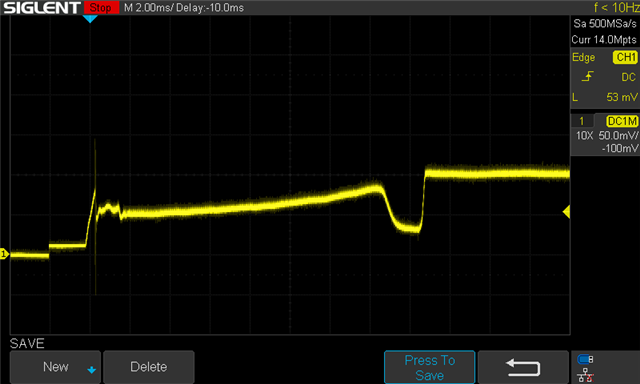
200us/div: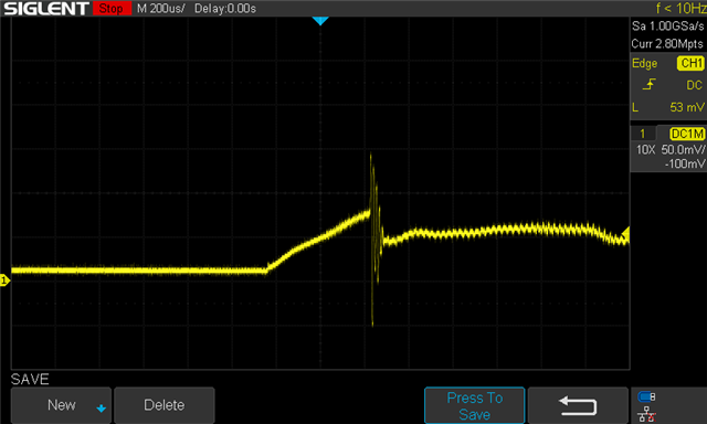
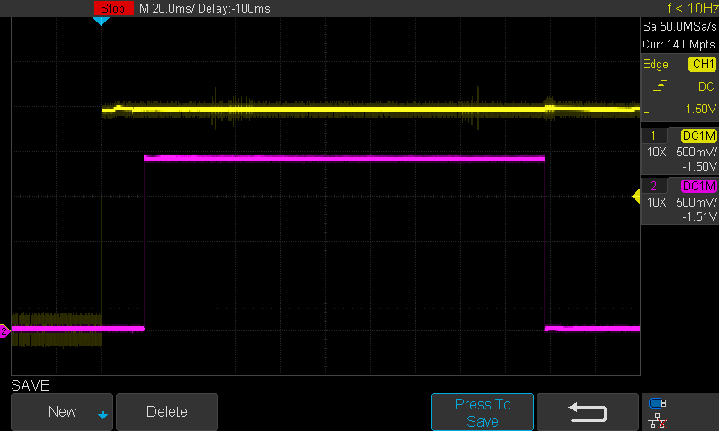
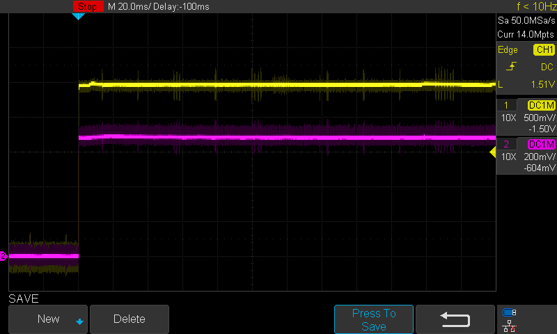
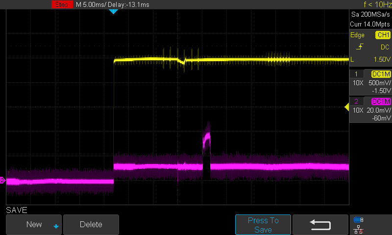
Also, below is a capture of the output voltage, which appears to be correctly showing the slow ramp up caused by the DVDT capacitor and the correct output voltage at steady-state: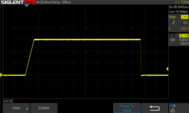
I also have traces for the ILIM output for both of the secondary eFuses, as well as captures at SWEN, PGOOD, DVDT, etc., but I don't want to share so much as to confuse anyone.
I'll also provide the schematic for the eFuse part of the circuit below:
Also, below are screenshots of the layout for each layer. Unfortunately, we're only using 4 layers for the board, which may be detrimental. I know that I do not have optimal grounding, and it was a challenge to get all signals routed between the eFuses without cutting off my input or output traces.
Layer 0 (top):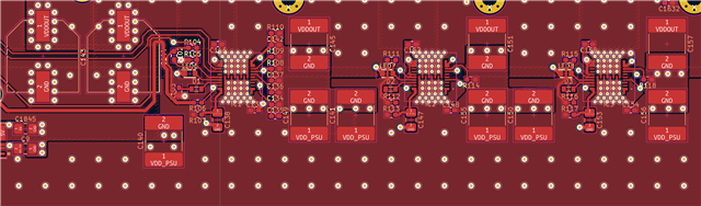
Layer 1 (inner):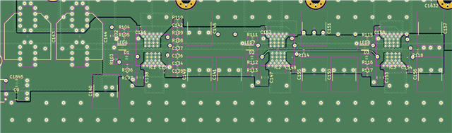
Layer 2 (inner):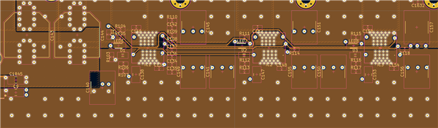
Layer 3 (bottom):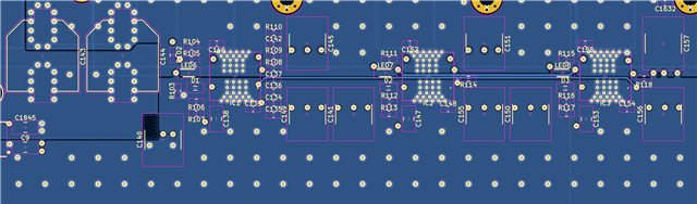
My hunch is that whatever is causing the spike and ringing in the ILIM signal is causing the eFuse to shutoff, but I'm hoping someone who understands this chip better than myself will see a smoking gun. Anyone have ideas?