This thread has been locked.

If you have a related question, please click the "Ask a related question" button in the top right corner. The newly created question will be automatically linked to this question.

LM7480-Q1: Priority mux and inrush current

Part Number: LM7480-Q1

I'm looking at Q5 in Figure 15 of the "Six System Architectures With Robust Reverse Battery Protection Using an Ideal Diode Controller" document.

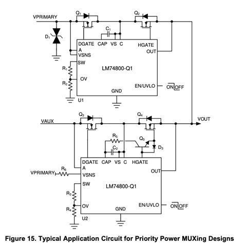
Q5 is added to improve the turn-on time of the secondary supply HGATE FET Q4.

Doesn't this defeat the inrush current protection, for cases where the system is powered up with the secondary supply only?

Is the purpose of speeding up the turn on of Q4 to reduce the need for a large output cap, which would otherwise be needed to prevent voltage sag during the changeover?

Thanks!

  • Hi Steve,

    Yes, your understanding is correct. Adding Q5 in the circuit will speed up HGATE FET Q4 turn ON and will disable inrush current limiting for the secondary rail.

    We do have a work around circuit to have inrush current limiting during startup while also having fast turn ON of secondary HGATE while transitioning from primary to secondary. Let me check if we can share this circuit with you. 

  • Thanks for the prompt reply.

    In case it matters, this is a case where there is a primary supply (11-14VDC) and a secondary supply (regulated 12VDC). Both supplies have a battery, but we don't want to draw from the primary battery for very long--a few seconds is okay. But we also can't have any substantial reverse current flow into either supply. There is a control signal that can be used to select between the primary and secondary supplies. The primary voltage even when on battery may be higher than the voltage of the secondary system. The voltage drop of a simple diode-OR is not acceptable on the secondary supply, but may be for the primary. So maybe an ideal diode on both, but the primary's ideal diode is controlled by looking at the control signal and voltage at the output node?

    It's mostly the switch-over time I'm worried about.

    Thanks!

  • I presume the inrush current limit with fast turn on is uses a pair of comparators and some state logic to notice the rising edge of VOUT vs falling, and enabling fast turn-on only when VOUT is above some limit, and disabling it when VOUT falls below a lower level. So inrush is active when VOUT is low (output discharged) and disabled when VOUT is mostly charged. More or less correct?

  • Hi Steve,

    Let me review your comments and get back to you by tomorrow.

  • Hi Steve,

    Yes, you will have to enable/disable the fast switch over circuit depending on whether the Vout is present/absent. If Vout is absent this means you are starting up and will require inrush current limit based startup, so disable the fast switch over circuit.