This thread has been locked.

If you have a related question, please click the "Ask a related question" button in the top right corner. The newly created question will be automatically linked to this question.

UCC2808-2: UCC2808A-2: How to fix the duty cycle

Part Number: UCC2808-2
Other Parts Discussed in Thread: UCC2808-1

Hi,

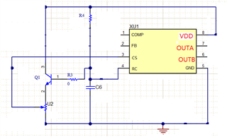
I use the chip UCC2808-2 and I would like to fix the duty cycle about ~40%. How to do it ?

I'm confused with COMP and CS pins functionnality. I read that "The CS pin is for duty-cycle control" (subject: UCC2808A-1: Open Loop Configuration) or "The duty is adjusted by COMP voltage" (subject : UCC2808-1: two questions about how to use).

I realized a lot of experiments. The most conclusive is : CS=not connected, FB=~0V (=it's the VCE voltage of NPN to realize a shutdown) and COMP=0.506mV (with potentiometer to tune the Vcomp). BUT I'm not confident about leaving CS unwired (!!!).

Do you have application note for a fix duty cycle ? Please can you give me your recommendation ?

Best regards

Eric

  • Hi,

    FB = GND, CS from your current sense resistor, a resistor from COMP to GND which value needs to adjust to work with CS saw tooth until you see 40% duty.

    Note, the device is assumed to work in close loop so tolerance can be absorbed by feedback loop control. Open loop would need your manual adjustment so IC tolerance can make from part to part different from 40%.  

  • Hi Hong,

    thank for your response.

    I want to work in open loop with ~40% of duty cycle, so I have NOT a current sense resistor for pin CS. What is the voltage to applied (with resistor divider) for CS pin ?

    Ok for FB = GND and COMP to GND with resistor value to adjust to have duty cycle ~40%. I will try it.

    Best regards

    Eric

  • Hi,

    You need CS with a saw tooth signal in phase with OUTA and OUTB to get the 40%. A simplest way is to use current sense.

  • Hi,

    Sorry I have no current sense in my application (not possible to add it). Only need OUTA and OUTB output with duty cycle ~40%. Now, I understand the CS fonctionnality.

    May be UCC2808 is not the correct component. I need OUTA/OUTB for push-pull topology, open loop, PWM 250kHz, fixe duty cycle ~40% , small package SOIC8. Do you have it ?

  • Hi,

    Others push-pull controllers are similar, you need to generate a saw tooth signal to CS pin in order to adjust the duty to 40%. Current sense is one way to obtain this saw tooth signal. You could also design a saw tooth signal without current sense with OUTA and OUTB signal. But no matter what you still need to provide a saw tooth signal to CS in order to adjust the duty to your need such as 40%.

  • Thank for your response.

    I have experiment this setup to have duty cycle ~40% : FB=GND, a resistor (=1MOhms) from CS to GND and COMP about 500mV. The duty cycle seems adjustable (by COMP voltage) with this configuration. But I don't understand why it's seems to work !!! Do you have explanations about it ?

    I have seen a project with a comparator voltage from RC to inject at CS (subject : UCC2808-1: two questions about how to use). I find this method smart. Do you have Application Note or other descriptions ? I need very small comparator chip reference.

    Best regards

  • Hi,

    I think what duty you get is maximum duty. No, I do not have. But you can search on the internet, or search digi-key to find a proper comparator you need. 

  • Hi,

    We have provided the device can do which may not be in your favor. But it is a solution from our side. Your simply say not solved in your favor does not help to move anywhere else. In this sense, your issue is resolved by our proposed solution. If you still insist your own idea, you can try looking for somewhere else.

  • Hi,

    How can I create a CS signal from RC signal to fix the duty cycle ~40% ? I tried with resistor divider to create, it's seems not easy.

    In the TI portfolio, do you have a SOIC8, push pull PWM outA/outB with fixed duty cycle ?

    Best regards

  • Hi,

    As already mentioned, all the push-pull controllers we have are similar and need to have CS saw tooth to adjust duty to a certain value < Dmax.

    The below is one possible way to generate CS saw tooth signal. U2 is can be replaced with a resistor divider after you get correct CS signal.

  • Hi,

    Thank. I will try it and gives news

    Best regards