On a development board, I have two LM22677 buck converters for two different voltage levels (adjustable at 12V, fixed at 5V). As per the datasheet section 7.3.4, the RT/SYNC pins of the two connectors are pulled low with 1k resistors and tied together with a 2N7002 N-channel MOSFET, Q1. Please note I accidentally routed the enable pins (7) to input power. On the actual board, those pins are bent up and soldered together with a jumper.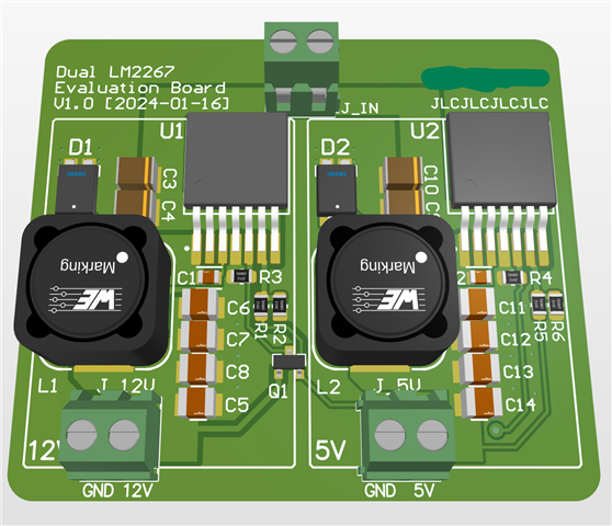
The datasheet then specifies: The two regulators will be clocked at the same frequency but slightly phase shifted according to the minimum off-time of the regulator with the fastest internal oscillator. The slight phase shift helps to reduce stress on the input capacitors of the regulator.
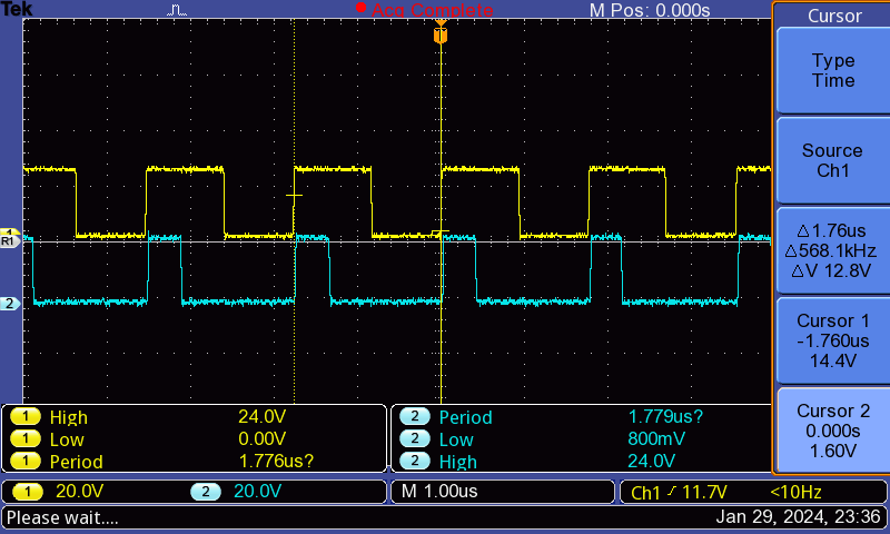
Therefore, I would expect that probing the SW pins of each converter would show a phase shift of the minimum off-time, around 200 ns. However, the actual scope shows that the two waveforms are exactly in phase.
Would I not expect to see a 200 ns phase shift? Am I misunderstanding the datasheet or have I designed the circuit incorrectly?