This thread has been locked.

If you have a related question, please click the "Ask a related question" button in the top right corner. The newly created question will be automatically linked to this question.

BQ40Z80: ROSC could not change when charge and dicharge

Part Number: BQ40Z80
Other Parts Discussed in Thread: EV2400

Dear Exeprt

We found some BQ40Z80 FCC coumd not change and RSOC alaways 100% when dischager and chager  the battery.
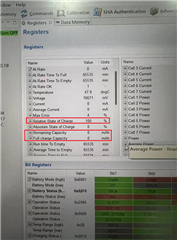
Bleow is our gg.file & log file ,and log file we just dischage the battery form 100% to 0% .

500-2-KUCUN.gg.csvGT500-0102..csv

Could u hlep to give some advice?

  • Hello,

    Does it only occur during discharge? 

    I noticed that update status is 0x0E, so I would assume a right ChemID was matched and learning cycle was done. Did you ever see this behavior when doing the learning cycle? 

    The reason why it reports 100% is because FCC is 0. FCC can drop to zero if any of the following happens:

    1- Very large current. Does it happen with smaller loads like 500mA?
    2- Very Large internal resistance. I did not see huge resistance update in gg file. 

    Regards,
    Jose Couso

  • Hello Jose.

    This is Sam from the end customer Ctechi. We reproduce this issue in our factory yesterday: After fully charged, discharge the battery pack with real 10W (we have 10 times scale):

    The 40Z80 can identify the 57mA (real 570mA), but the RemCap don't change!  until many hours later. Maybe this is the root cause. 

    Please refer to attached log file.  Thank you so much for your support!

    USB放电SOC不变-放完电.csv

  • Hey Chen,

    Today's a federal holiday so no one is in the office. We will get back to you tomorrow.

    Regards,
    Nick Richards

  • Thank you Nick!

    This is really a challenge issue. Let me introduce the whole story to Experts here. 

    End of last year, we get two BMS from JP market that FCC keep 0mAh. And we find two similar NG product (new product in warehouse for half year) also with 0mAh FCC (SOC is keep 100% whatever charge or discharge). We share the picture from EV2400 and the gg file to Gabriel WANG. (So Gabriel popped this issue to here E2E); 

    Last week (Middle of Feb.), we reproduced the similar issue with a new product from production line (not from warehouse), please refer to attached log file:

    During discharge, SOC keep 100% for long time. Then, we start log data for analysis. We find the 40Z80 can identify the current with 57mA (real 570mA because of 10 times scale), but RemCap keep 1.7Ah (equal 17Ah. But the real cell capacity is 27Ah) without any change.  But hours later RemCap and SOC start to decrease (from the log, it looks like just 1Ah discharge with the same RemCap and SOC. The 1 Ah is looks like the different of 1.7Ah ~ 2.7Ah part). After fully discharged, 5 hours later we charge it fully. Now the FCC increase from 1.7Ah (real 17Ah) up to 2.5Ah (real 25Ah). 

    It looks like some algorithm block the RemCap update. Thank you all Experts. Thanks for your support!

    DuringDischargeKeep100%ForLongTime-FulllyDischargeRest5HoursFullyChargeRest5Hours.xlsx

  • Hey Chen,

    Thank you for sending the files. I will need more time to look through them. However one thing I noticed is that fltRemQ and TrueRemQ are being updated  properly. I will need to consult some other members of the team regarding this. Thank you for being patient.

    Regards,
    Nick Richards

  • Hey Nick,

    Thank you for your support. I am online to wait your good news. Because it is really a big issue, lots products in production line, and wait to shipping. We have to find the root cause, and fix it before shipping. Thanks.

  • Hello Chen,

    I have checked all the usual suspects regarding this problem and have found that everything seems fine in your settings. Have you tried a test with a constant discharge at a higher rate (maybe around 500 mA). I want to see if a higher discharge will cause the same problem.

    Sincerely,
    Nick Richards

  • Hi Nick,

    Thank you for your support. I think you 500mA is detected current and the real current is 5000mA, since we have 10 times scale. Right? Before your confirmation, we will do the 2500mA (real current 25000mA) test. Because 2.5A (25A in real) discharge is the nominal current.

  • Hi Nick,

    Today, we charge the battery pack to full. But during charge the FCC change from provious 2.5Ah (real 25Ah) down to about 1.5Ah (real 15Ah)! Unforturntaly we did not log the charge process. When we find the FCC change, we start log it. And close fully charged, the FCC jump to 2.5Ah again!!! Please check the log file in attachment.

    After fully charged, we start discharge also. When close fully charged, FCC changed little also (from 2.55Ah to 2.49Ah). You can check the data in the same attached log file.

    AC-chg-dis-chg-2024-02-22.csv

    Thanks for your support.

    B.R.

    Sam CHEN

  • Hey Chen,

    Yes, run a test with a real current at 5000mA. Also, please capture a log file of the entire test. I would have like to have seen when FCC changed from 2.5 down to 1.5 in the log.

    Regards,
    Nick Richards

  • Hey Nick,

    Thanks for your feedback. I am discharge it with 510ma (real 5100mA) now. will feed back to you hours later.

    B.R.

    Sam CHEN

  • Hey Nick,

    Please refer to 500mA (5000mA real) discharge log data. But this time, the FCC is normal. Do you think the false soldering might make the incorrect FCC?

    5AdischargeLog.csv

  • Hey Chen,

    It is possible that the false soldering that could have cause the issue. Also, by running more test the gauge is continuing to learn the true FCC for the battery  you are using. I would recommend continuing to run more tests to see if you keep getting good results. It is important that the gauge detects valid charge  termination when charging the battery. This will ensure that FCC is being updated properly.

    Regards,
    Nick Richards

  • Hey Nick,

    We will try to catch the unnormal FCC update, and log it. According to the technical reference manual, I have the feeling that because of some reason (for example false soldering, EMC... make the incorrect voltage detect, incorrect resistance detect...), some thing make the FCC update to 0mAh. I want to do some more test trying to reproduce it.  So, I want to consult you what kind of test we should do, so that it is possible to reproduce the problem. 

    Thank you for your support!

    7.5 FullChargeCapacity(FCC), RemainingCapacity(RemCap), and RelativeStateOfCharge(RSOC) The Impedance Track algorithm applies QMax, impedance, temperature, voltage, and current data to predict the runtime FullChargeCapacity(), RemainingCapacity(), and RelativeStateOfCharge(). These values are updated if any of the following conditions are met, reflecting the battery capacity at real time.

    • QMax update occurs

    • Ra update occurs

    • At onset of charge and discharge

    • At exit of discharge

    • Every 5 hours in RELAX mode

    • If temperature changes more than 5°C

  • Hey Nick,

    One thing I have to remind that the cell we are using is LifePO4, not NCM. Do you think 40Z80 is OK for LifePO4? 

    B.R.

    Sam CHEN

  • [LFP_RELAX]: This is an option for LiFePO4 chemistry. This flag can be enabled even if non-LiFePO4 chemistry is programmed. The BQ40Z80 device will check for the chemistry ID (that is, ChemID = 4xx series) before activating this function. The LiFePO4 has a unique slow Configuration relaxation near full charge. Detailed, in-house test data suggests that the relaxation after a full charge takes a few days to settle. The slow decaying voltage causes RSOC to continue to drop every 5 hours. Depending on the full charge taper current, the fully settled voltage could be close to or even below FlatVoltMax in some cases. For the chemID 4xx (LiFePO4) series, the condition to exit the long RELAX mode is if the pack had previously charged to full or near full state, and then either a significant long relaxation or a non-trivial discharge has happened, such that when in relaxation, the OCV < FlatVoltMax. The QMax update is disabled because DOD will not be taken as long as it is in LFP_RELAX mode. By the time the gas gauge exits the LFP_RELAX mode, the OCV is already in the flat zone. Therefore, the QMax update takes an alternative approach: Once full charge occurs ([FC] bit set), DOD0 = Dod_at_EOC is automatically assigned and valid for a QMax update. [VOK] is set if there is no QMax update. If QMax is updated, [VOK] is cleared. The DOD error as a result of this action is zero or negligible because in the LiFePO4 table, OCV voltage corresponding to DOD= 0 is much lower.

  • Hi Nick,

    Yes, you are right! If the voltage detect circuit has false soldering, it might be effect the FCC update incorrect.

    During weekend, we did such test: we disconnect the voltage detect cable for cell 2. In two days, there many times FCC update, and the Min. is 0mAh! . Even we still not find any NG product with false soldering issue, But this might be a possible reason. Please refer to attached log file. We need you comments about this. Thanks for your support.

    Cell2-screw looses-relaxTest.xlsx

    B.R.

    Sam CHEN

  • Hi Nick,

    Today, we found another product, with normal discharge, but the FCC update down to 9mAh! Please refer to attached log file. This product comes from production line. Previously it is a normal products with correct SOC display. After many times charge discharge cycle, now, it is unnormal.

    USB-discharge-FCCupdateTo9mAh.csv

    B.R.

    Sam CHEN

  • Hey Chen,

    The BQ40z80 is perfectly fine for LFP. For your test of disconnecting the voltage detect cable is what I would expect to happen. This will cause pack voltage to rapidly drop which is seen in the log file. I would also expect some of the protections to be trigger as well in this type of test. For the unit from production line, does this gauge have the same gg file as the ones you sent before?

    Regards,
    Nick Richards

  • Hey Nick,

    Thanks you for your information. It is great that BQ40Z80 is perfectly fine for LFP. 

    Yes, when the voltage detection cable is disconnected, the voltage will be rapidly drop and increase. In this case the under voltage and over voltage will be protected. 

    Yes, the unit from production line is the same configuration as we sent to you before, because all are the same project.

    Today, we reproduce again the 0mAh with a normal products from production line: We just use a USB 5V2A 10W to discharge it, the FCC drop to 0mAh! Please refer to attached log file. I think the small current might be to point to reproduce.

    USB-discharge-0mAh100% -2024227.csv

    B.R.

    Sam CHEN

  • Hey Chen,

    Can you please send the gg file from this unit and also send a gg file from a unit that is reporting the FCC accurately. I want to compare the two, more specifically, see if there is anything abnormal in the Ra table.

    Regards,
    Nick Richards

  • Hi Nick,

    Thanks for you support. Please refer the standard mass production gg file. As for the abnormal gg file, you can refer to the first original information send by Gabriel "500-2-KUCUN.gg.csv"

    001-230722-GT500-BmsApp-A2.gg.csv

  • Hey Chen,

    I checked the gg file of the defective unit and noticed in the lifetime data that there were 4 reported events of Cell Over Voltage and 10 reported events of Cell  Under Voltage. Do you know how these events were caused or why these protections were tripped?

    Regards,
    Nick Richards

  • Hey Nick,

    Over voltage and undervoltage protection is normal action during using, because user will fully charged, and fully discharge the battery pack. Those will effect the abnormal FCC?

    Regards,

    Sam CHEN.

  • Hey Chen,

    It is possible that this could be cause of the issue. Protections should not be tripping under normal operation. Over voltage and under voltage protection  thresholds should be set at points that are outside of the normal operation voltage range.

    Regards,
    Nick Richards

  • Hey Nick,

    No, I don't think so. Even over voltage and under voltage protection happen, but those should not cause incorrect FCC. 

    We still not find the root cause. Do you think the chip itself have problem? (NG chip?)

    We have to continue to release products to our customer. For coming shipping, we want to change some setting for make the FCC as no change as possible. Which configuration do you think is suggest to change? Thanks for your support.

    Regards,

    Sam CHEN

  • Hello Chen,

    It is not out of the realm of possibilities that the physical chip could be damaged somehow. There is not much that can be done to make FCC update as little as possible (this is how the gauge is designed). The only way to reduce the number of FCC updates is to disable smoothing.

    Regards,
    Nick Richards

  • Hey Nick,

    Thanks. But you can see from the gg file that we disable the smoothing already.

    Today, I want to share new information with you: We found our structure design have a big bug. We use screw to connect the cell B- and B6 to BMS. In some products, the screw is not so tight, the resistance of cell B- to BMS B- is too high during high current charge or discharge. (The same as cell B6 to BMS B6). When we discharge with 27A (2.7A for BMS), the voltage of BMS detected B1 will drop down to 280mV compared to other cells. And many are 180mV(it is also unnormal). The normal is around 40mV.  Do you think this is the root cause for FCC drop to 0mAh?

    Regards.

    Sam CHEN

  • Hey Chen,

    Yes it is possible that this could be the cause. Anything abnormal found in the units that reported 0 mAh for FCC could be causing the behavior. The abnormal voltage drop could be leading the gauge to calculate incorrect Ra table values.

    Regards,

    Nick Richards