This thread has been locked.

If you have a related question, please click the "Ask a related question" button in the top right corner. The newly created question will be automatically linked to this question.

BQ25180: Recharging supercap

Part Number: BQ25180

Hello, 

We're trying to use the Bq25180 to recharge a 3.3v 0.07F supercap.

At the moment, it's possible to communicate well with the chip, so the interface is well established.

For the default register values, the chip doesn't recharge the supercap at all (the supercap is empty of charge and keeps in this situation).

Still using the default register values but recharging the cap directly with the power supply to the voltage of VIN, the chip seems to maintain the cap voltage of around 1.4V.

About the above, I have some questions:

1. Why it keeps 1.4V? 

2. What should be a recommended byte write sequence in order to configure the chip to recharge the cap to around VIN voltage? It's desired to have the cap recharged by the chip even if it's fully discharged at the beginning. The current of recharge should be around 500mA. 

Thanks. 

  • Hi,

    For the default register values, the chip doesn't recharge the supercap at all (the supercap is empty of charge and keeps in this situation).

    Can you please share all the register values for additional context?

    1. Why it keeps 1.4V? 

    I'm not sure why charging would stop at 1.4V, it should be charging. Do you have a load connected to the SYS pin or the cap directly? It should charge up to the regulation voltage set in the VBAT register (default value is 4.2V). Can you please share the device register values at this point, and if possible, a waveform of VBAT?

    2. What should be a recommended byte write sequence in order to configure the chip to recharge the cap to around VIN voltage? It's desired to have the cap recharged by the chip even if it's fully discharged at the beginning. The current of recharge should be around 500mA. 

    The device will by default recharge the BAT pin once it falls 100 mV below the regulation voltage. This can be changed to 200 mV, but it sounds like you would prefer it at 100 mV. Setting the charge current to 500 mA can be done by writing register 0x05, bits 6-0, to 0x4D.

    Best Regards,

    Juan Ospina

  • Hi Juan,
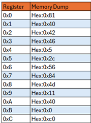
    The registers are as follows:


    Actually there's nothing connected to the battery other then the BQ25180.

  • Hi Emanuel,

    The register dump doesn’t seem to indicate anything that could be limiting charge, though your charge current is only set to 10 mA. Can you share the schematic of your BQ25180? 

    Also, if possible please share waveforms of input voltage, system voltage, and output voltage.

  • Hi Juan,
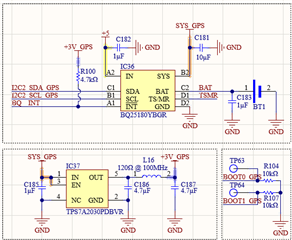
    the schematic is shown below:


    where the line +3V_GPS is the main power supply for the mcu that communicate with the BQ.

    Best regards.

  • Hi Emanuel,

    Can you please share the TSMR circuit as well. Also can you attempt to charge with the SYS_GPS rail disconnected from the load. If the waveforms are available those would be most helpful.

    Best Regards.