This thread has been locked.

If you have a related question, please click the "Ask a related question" button in the top right corner. The newly created question will be automatically linked to this question.

TPS62933: Design review and validation

Part Number: TPS62933

We are making a cost-effective power distribution board for our drone. 

The board is supposed to supply :

  • 20A at 17.4V to a 4in1 ESC (powering 4 BLDC motors) max.

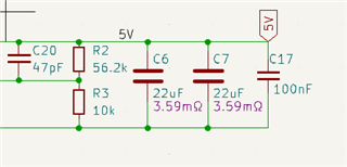
  • 5V to flight controller at 3A max.

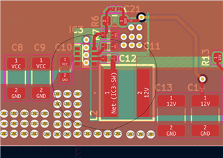
  • 12V to video transmission system at 1A max.

Components have been bought but before board manufacturing, requesting a review of the work. We have tried to follow layout guideline from the datasheet as much as possible.

5V BUCK - 800kHZ

12V BUCK - 500KHZ

Files PDBV2-D01.pdf

Schematic 

PDBV2-D01PCB.pdf

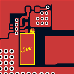
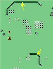
PCB individual layers

The mechanical dimensions of the board were decided beforehand, we are not allowed to make it any bigger or smaller.

Thanks in advance!

  • Hi Balkrushna,

    Thanks for using TPS62933! Below are my review comments.

    For schematic,

    1. Your output cap grm31cr71a226ke15l is 10V rating, cannot be used in 12Vout rail.

    2. Your BOM list has Cff component, while your schematic doesn't have. You can add a Cff place in parallel with Rfbt, in case further debugging needed (e.g. to optimize loop response).

    3. The 5V rail is configured to 4.98V output, not 5.3V in your note below.

    For layout,

    1. Below SW node size doesn't need to be that large, you could decrease it to inductor pad size. Generally SW node is noisy node, we don't want it be very large.

    2. You can move Vout sensing traces from Layer2 to Layer3, to avoid Layer1 SW disturbance.

  • Hi Miranda, thank you for the suggestion and corrections. Please find the attached the changes we have made.

    1. 22uF capacitor changed to CL32B226KAJNNNE - 22uF 25V capacitor.

    2. Value of Rfbt (5.3V) corrected on the footprint. 56.2kOhms

    3. SW layout for 12V buck corrected.

    4. Feedback paths routed to Inner layer two.

    Since this is for a drone application and the board might be subjected to hot plugging and disturbances from the electronic speed controller, we have added 330uF 63V Capacitor between Vin and GND of the bucks. Part no - EEU-FS1J331L. Is this enough or do we need to increase the input capacitances?

    Thank you again for the help!

  • Hi Balkrushna,

    If hot-plugging is always in your application, maybe you can add a hotswap IC at input: https://www.ti.com/power-management/power-switches/efuse-hotswap-controllers/products.html?keyMatch=HOTSWAP 

    Using large Cin may cause high inrush current during power on. I think additional soft-start circuit or hotswap IC is needed.