This thread has been locked.

If you have a related question, please click the "Ask a related question" button in the top right corner. The newly created question will be automatically linked to this question.

BQ25720: BQ25720RSNR

Part Number: BQ25720

HI 

We are using the battery charger BQ25720RSNR in laptop project. We are using three cell battery. We are facing issue with this battery charger.

When we insert the DC jack (J17) and turn on the charger the battery charger is working fine and generating the output. But when we do multiple cycles of on and off of battery charger the battery charger stops generating the output. We checked the DC jack input power. It is coming proper 19.5V input but not generating the system power.

We have also attached the battery charger schematic for your reference. We have checked the voltage at C385 (VCC_CHGR_EMI_VIN_R) it is coming but we are not able to get any voltage at TP164 (VCC_VBATA).

We have also checked the signals (BC_HS_DRV1, BC_LS_DRV1) which is driving the dual mosfet (Q14 and Q15), It is low. When this issue is not come and battery charger is generating the output properly at that time these signals are at 5V level.

Kindly check and help to resolve this issue.

  • Hi Udesh,

    When you say "we do multiple cycles of on and off of battery charger", do you mean you turn on/off the adapter? or remove/plug in adapter?

    What is the state of the CHRG_OK signal? Can you capture the register map and attach here?

    Best Regards,

    Munir

  • HI Hasan

    When you say "we do multiple cycles of on and off of battery charger", do you mean you turn on/off the adapter? or remove/plug in adapter?

    Ans: Turn on/off the adapter.

    What is the state of the CHRG_OK signal? Can you capture the register map and attach here?

    Ans: When the charger is working fine, CHRG_OK signal is High but when we are facing the issue, CHRG_OK signal is low. It is low as the pull up voltage is VCC_3V3_DSW_LDO and this voltage will come when battery charger will generate the output (VCC_VBATA).

    Register map setting attached:

    Charger(BQ25720)_Command_Registers_DUMP.xlsx

  • Hi Udesh,

    The charge status register does not show any fault. Are you sure that the register map was dumped after the charger issue occurs or when CHRG_OK goes low? We need the amp after the fault occurs.

    Basically, we would like to see what fault happened that it caused CHRG_OK to go low by looking at the charge status register 20h. I am suspecting there could be input over voltage fault due to adapter on/off several times. But we need to be sure from the register dump.

    Best Regards,

    Munir

  • HI Hasan 

    Please let me know the proper procedure to get the resistor map after the issue occur.

    This is the general resistor map dumped we have got from the working board.

  • Hi Udesh,

    You already extracted the register map properly from the working board. You will just extract it again when the board stops working.

    You said that there is voltage  atVCC_CHGR_EMI_VIN_R when the board stops working so the register map should still be available.

    Best Regards,

    Munir

  • HI Munir

    As power is not coming so EC is also not power on. I am not able to get the logs when this issue occurs. So kindly let us know how we can take the logs when issue occurs.

  • Hi Udesh,

    I might have misunderstood your statement when you said 'We have checked the voltage at C385 (VCC_CHGR_EMI_VIN_R) it is coming but we are not able to get any voltage at TP164 (VCC_VBATA).'

    To clarify,

    1. You have a valid voltage at VCC_CHGR_EMI_VIN_R, the charger outputs VAA or REGN but not VCC_VBATA. Is that correct?

    2. Are you powering the EC from VCC_VBATA? If that is the case then please supply a valid power to EC to access the registers. However, if the charger is not getting any power then it is not possible to access the registers. In that case we need to find the issue in some other way.

    3. I notice that the charger VBUS connection is not really according to the checklist. Our recommendation is to draw VBUS power from VCC_CHGR_EMI_VIN_R. Refer to the checklist from this link here. However, it is not clear yet if that is responsible for the issue.

    4. Can you replicate the issue and show scope captures of VADP_IN, VCC_BCHGR_IN, VCC_CHGR_EMI_VIN_R , VCC_VBAT_A and BC_VDDA ? Please show the whole sequence from turning the adapter on/off to when VCC_VBATA turns off. 

    Best Regards,

    Munir

  • HI Munir

    1. You have a valid voltage at VCC_CHGR_EMI_VIN_R, the charger outputs VAA or REGN but not VCC_VBATA. Is that correct?

    Ans: Yes REGN is coming but VCC_VBATA is not coming.

    2. Are you powering the EC from VCC_VBATA? If that is the case then please supply a valid power to EC to access the registers. However, if the charger is not getting any power then it is not possible to access the registers. In that case we need to find the issue in some other way.

    Ans: Yes we are powering on the EC by VCC_VBATA. Charger is powering on so we can access the resistor. Give me sometime I will think some other way to access the resistor.

    3. I notice that the charger VBUS connection is not really according to the checklist. Our recommendation is to draw VBUS power from VCC_CHGR_EMI_VIN_R. Refer to the checklist from this link here. However, it is not clear yet if that is responsible for the issue.

    4. Can you replicate the issue and show scope captures of VADP_IN, VCC_BCHGR_IN, VCC_CHGR_EMI_VIN_R , VCC_VBAT_A and BC_VDDA ? Please show the whole sequence from turning the adapter on/off to when VCC_VBATA turns off. 

    Regarding the question 3 and 4 give me sometime i will check in this week and share you all the waveforms.

  • Hi Udesh,

    Alright. Thanks for letting me know.

    Best Regards,

    Munir

  • Hi Munir, 

    We have captured the waveform which you have asked to check.

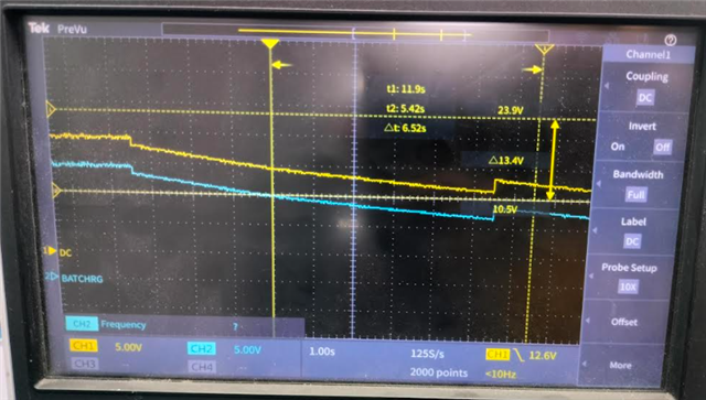
    Please find the attached document for your reference. We have also observed the condition where issue is happening every time. We have also attach the waveform of this and also explain the condition in which we are observing issue every time.

    Kindly check and help us to find the root cause of this issue.

    BQ25720RSN_battery_charger_issue.docx

  • Hi Udesh,

    Have you been able to capture the register map when the VCC_VBATA stops output? 

    Regarding the scope capture on the last page, the description does not sound consistent. For example, the description point 3 says that the adapter is turned on in region 1 but the image shows that the voltage is decreasing in region 1 showing that power was removed. Also, how does BATCHRG(VCC_BCHGR_IN) have 20V when DC (VADP_IN) is 0V? By any chance do you have the names of the traces interchanged?

    Regarding the case in region 2, That might be because of the activity of STD_ADPT_CNTRL_GPIO turning on/off Q1/Q2.  

    Best Regards,

    Munir

  • HI Munir,

    DC(VADP_IN) is not 0V. Please find the waveform of Region 1 again.

    Also if we can able to capture the register map we will send it to you. 

    Regarding the case in region 2, That might be because of the activity of STD_ADPT_CNTRL_GPIO turning on/off Q1/Q2.  

    Ans: STD_ADPT_CNTRL_GPIO pin is not connected to EC. We have no mount the series register so this pin is not creating any impact.

  • HI Munir

    Please find the register dump when we are facing the issue on the board.

    ChargeOption0: e70e
    ChargeOption1: 3300
    ChargeOption2: b7
    ChargeOption3: 1076
    ProchotOption0: 4a81
    ProchotOption1: 41a0
    ADCOption: 2000
    ChargeOption4: 48
    Vmin_Active_Protection: 6c
    OTGVoltage: 9c4
    OTGCurrent: 3c00
    InputVoltage: 3b00
    VSYS_MIN: 5c00
    IIN_HOST: 5000
    ManufacturerID: 40
    DeviceID: e1

  • Hi Munir

    Kindly update.

  • Hi Udesh,

    It looks the board was damaged. Could you replace the IC to see if you can revive the board?

    Regards,

    Tiger

  • HI Tiger 

    Board is not damage. This board is working and we are facing this issue in all the boards.

    Looks battery charger is misbehaving. Can you please check the complete waveform and try to find the solution ?

  • I will suggest you checking the charger status register and reset the error if any. Could you provide register 0x20 status value?

    Regards,

    Tiger

  • HI Tiger 

    We have captured the resistor dump both the cases i.e when board is working fine and when we are facing issue.

    Resistor dump while facing issue:

    0x12, 0xe70e , 59150
    0x14, 0x0700 , 1792
    0x15, 0x3138 , 12600
    0x20, 0x8008 , 32776
    0x21, 0xb880 , 47232
    0x22, 0x5000 , 20480
    0x23, 0xcc00 , 52224
    0x24, 0x0000 , 0
    0x25, 0x0000 , 0
    0x26, 0x0000 , 0
    0x30, 0x3300 , 13056
    0x31, 0x00b7 , 183
    0x32, 0x0434 , 1076
    0x33, 0x4a81 , 19073
    0x34, 0x41a0 , 16800
    0x35, 0x2000 , 8192
    0x36, 0x0048 , 72
    0x37, 0x006c , 108
    0x3b, 0x09c4 , 2500
    0x3c, 0x3c00 , 15360
    0x3d, 0x3b00 , 15104
    0x3e, 0x5c00 , 23552
    0x3f, 0x5000 , 20480
    0xfe, 0x0040 , 64
    0xff, 0x00e1 , 225

    Resistor dump when board is working:

    0x12, 0xe70e , 59150
    0x14, 0x0000 , 0
    0x15, 0x3138 , 12600
    0x20, 0x8000 , 32768
    0x21, 0xb800 , 47104
    0x22, 0x4100 , 16640
    0x23, 0xcc00 , 52224
    0x24, 0x0000 , 0
    0x25, 0x0000 , 0
    0x26, 0x0000 , 0
    0x30, 0x3300 , 13056
    0x31, 0x00b7 , 183
    0x32, 0x0434 , 1076
    0x33, 0x4a81 , 19073
    0x34, 0x41a0 , 16800
    0x35, 0x2000 , 8192
    0x36, 0x0048 , 72
    0x37, 0x006c , 108
    0x3b, 0x09c4 , 2500
    0x3c, 0x3c00 , 15360
    0x3d, 0x3b00 , 15104
    0x3e, 0x5c00 , 23552
    0x3f, 0x4100 , 16640
    0xfe, 0x0040 , 64
    0xff, 0x00e1 , 225

    Kindly check and help to resolve this issue.

  • It shows system undervoltage protection SYS_UVP. Please clear this fault before restart. 

    Regards,

    Tiger

  • HI Tiger, 

    Please help to brief this. Kindly let us know how clear this fault.

  • HI Tiger, 

    There is resistor setting from SW, as battery charger is not generating the output power so my controller is also not power on. Kindly me know how we can clear this resistor in this case.

    Also we will set this resistor one time, is it permanent setting or the temporary ?

  • Hi, Udesh,

    You can write 0x8000 back to REG0X20 to clear the fault. The register just likes RAM, you need to write them again when power is recycled.

    The SYS_UVP fault may arise from the test without battery. Why not install the battery and run the test again?

    Regards,

    Tiger

  • HI Tiger

    My Embedded controller is not powered on when we face this issue. So i can not be able to clear this fault. Can you please check and help to find the another way to clear this fault or is there any HW control on this. 

  • My other suggestion is to power on reset (POR) to clear the fault, please wait longer until the voltage is reduced to ground.