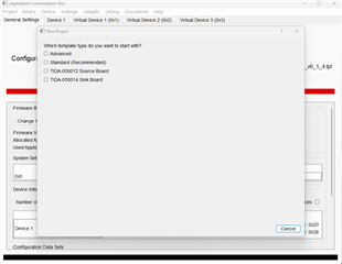
We are working on a project involving a TPS65987D USB PD controller where the device can source up to 60W. Similar to the USB-C-PD-DUO-EVM board, our board can provide the controller with 5v, 9v, 15v and 20v output voltages using the GPIO pins, but it doesn't seem like there is a way to hardware strap the controller to the correct configuration. Is there a configuration file you can provide us to get our board working properly? We are using an external flash AT25SF041B, happy to send over our schematic if needed.


