This thread has been locked.

If you have a related question, please click the "Ask a related question" button in the top right corner. The newly created question will be automatically linked to this question.

LM5116 VOUT circuit debug

Other Parts Discussed in Thread: LM5116

Hello Eric,

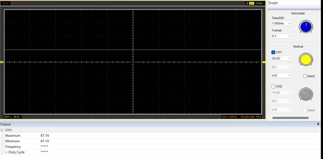
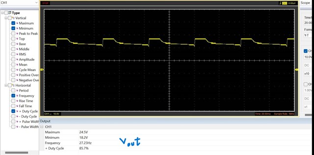
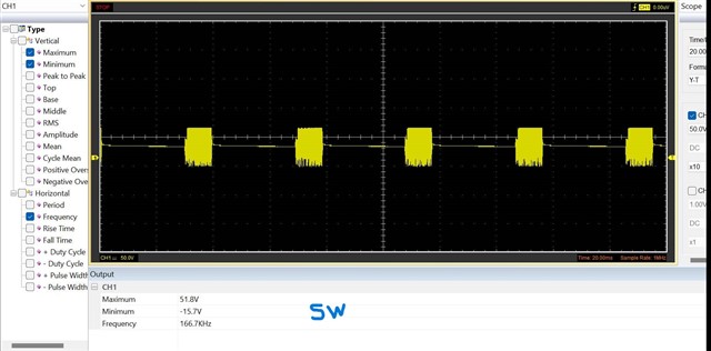
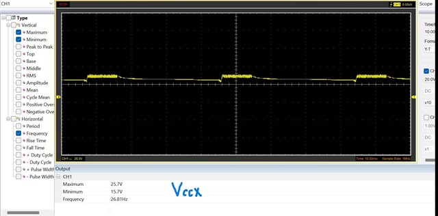
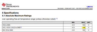
I have a Vout voltage greater than the Abs Max of the VCC pin (24V). So based on our discussion, I think I will need to supply VCC externally (like 12V).
You suggested connecting the Ext VCC voltage to the VCC pin through a diode and removing the R_vccx resistor. It means I should not use the VCCX pin and it is connected to the
PGND.

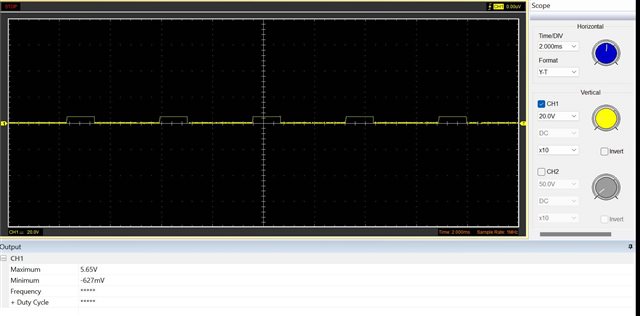
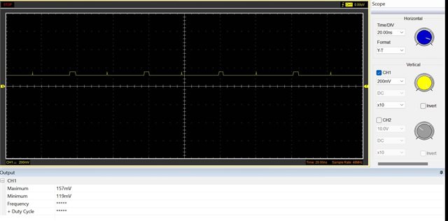
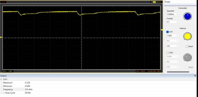
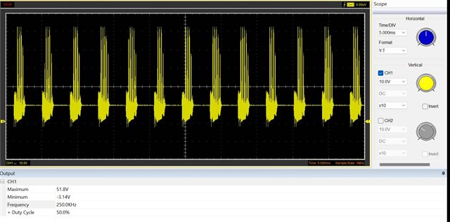
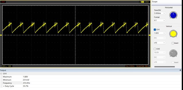
On the other hand, I used to start up delay around 250ms to achieve a constant input (around 48 volts ) that it was created by the Enable pin.
It means before the 250 ms (during start-up), I have VCC>Vin. Do I need to place one diode between the Input voltage to the Vin pin of the LM5116?(like a pdf file)

if your answer is yes , Does the 1n4007 is okey ?or like the Evaluation board  I used the CMPD2003 .

Thank you so much!

Leila

     LM5116 with External Vcc.pdf     

  • Hello Leila 

    Please connect the VCCX pin to ground.

    Supply external 12V through a diode (cathode to VCC, anode to the external 12V)  

    The best way is to enable the external 12V together with LM5116, but if you cannot, I think it is okay to connect a diode at the VIN pin

    In your schematic you connected HB to the external 12V, which is wrong. 

    -EL 

  • Hello,

    Thank you for your quick reply.

    Do you mean I need a bootstrap diode(D1) and an additional diode(D_vcc) for external supply? (attached)

    Do you mean I use a delay circuit for 250ms for connecting 12 volts? if not how can I enable the external 12v with LM5116 synchronously?

    Thanks again,
    Leila

    2335.LM5116 with External Vcc.pdf

  • Hello Leila 

    Yes, now the external 12V connection is correct. 

    Yes, if the external 12V is enabled together with VIN, you don't need to worry about the issue. 

    -EL

  • I am closing this thread since I have not heard from you for sometime.
    If you are still trying to resolve the issue, please feel free to open a new thread. Thanks
    - EL

  • Hello Eric,


    I changed my inductor to 53 uH. Unfortunately, I couldn't get a good result. Now, the output is 2.5 volts and when I connect to load(R=6.8ohm), the inductor creates a noise very loudly.

    Please help me to find my mistake to obtain a good result (24v).
    I checked all absolute maximum ratings of the LM5116( based on page 5 of the datasheet ). I think all of them are in range roughly. (Pdf file attached)

    All output signals are attached .

    Best regards,
    Leila

    Result comparison.pdf

  • Hello Leila

    Looks like the converter is unstable now and you need to adjust the loop compensation component values using the Quick Start calculator.  https://www.ti.com/lit/zip/snvu051 

    By the way, why did you change the inductor value to 53 uH?

    -EL

  • Hello Eric, 

    Thank you for your quick reply.

    Based on the last discussion we had. I chose  80% for ripple current, and then the value of the inductor was equal to 23uH (based on the LM5116 quick start,).  After that based on the date sheet and your advice, I decreased the ripple current to 25 % as it is better between 25% to 40 %. The value of the 53uH is selected for 25% ripple current. 

    Br, Leila

  • Hello Leila

    You have to adjust the loop compensation after changing the inductor value. If you did already, please share the Quick Start file .

    - EL 

  • Hello, 

    Yes. I did( attached) .In page two , you can see the new values of some components.

    Thank you. 

    Br, LeilaLM5116 quick start _v04.pdf

  • Hello Leila

    Would you please try Ccomp = ~57nF , RCOMP=~1.1kOhm and check if any improvement ? If, there is an improvement, please reduce the bandwidth FC below 12kHz and try the new CCOMP, RCOMP values.

    -EL  

  • Hello Eric,

    Thank you for your comment.

    I changed R_comp and C_comp, and the level of the output increased to 10 volts but the Inductor had an audible noise more than before. Then I changed the bandwidth to 12KH and then I replaced them with new values (R_comp: 53K, C_comp:2.5 nf) After that I checked the output again, the output had a large ripple. Additionally, I changed R_ramp and C_ramp to new values. After that, I got a strange result because the values of Vin, Vout, and SW were the same ( even when I changed the input, they changed). I think, I made a mistake during the soldering and then LM5116 is burnt out. What are your opinions?

    Best regards, 

    Leila

  • Hello Leila

    I agree with you. I think your board/ the device is damaged now. 

    -EL

  • Hello Eric,


    I changed my board and I made some improvements like changing the Inductor to 57 uH, the compensation loop to the (R=111K, C= 560pf), and RAMP components( R=128K, C=1300pf). As you can see the output improved but It has ripple( attached ). Then I started to check other test points like VCCX ( I should mention that I didn't use external VCC) and also SW( attached ). During the check of different test points like RT, I don't know, what did I do so that I lose suddenly the output.


    I have two question:

    1. The level of the VCCX is out of the range that recomend in the data sheet, Is it okay?


    2. How can I check the LM5116? Because I tested the two MOSFETs, diodes and Inductor. They are okay.`
    Now I am doubt between the PCB and LM5116.

    Thank you,
    Br, Leila

  • Hello Leila

    1, The abs max of VCCX is  only 16V. The device will be damaged if VCCX>16V

    2. Please follow this

    1. Replace the IC
    2. Set the power supply current limit ~0.1A-0.3A
    3. Gradually increase VIN without load
    4. Check these pins one by one step by step  EN, UVLO, VCC, RT, SS, COMP, SW and VOUT
    5. Check inductor current.

     -EL

  • Hello Eric,

    Thank you for supporting and helping me.

    Unfortunately, during the desoldering, I missed the board. Now, I am going to order a new one. I tried to apply all your comments on the schematic(attached ).

    I set the values of the parameters by initializing the BW to 25KHZ and F_SW to 250KHZ. Additionally, the value of the Ripple current is set at 25% and the current limit at 15%.

    I have a question, can I set the minimum input voltage same as the output voltage( 24 volts)?

    Please put your comments and help me how to remove the ripple in the Vccx for the new edition.

    Br, LeilaBuck_2ndR_V01.pdf


    Buck_2ndR_V01.pdf

  • Hello Leila 

    No, the input voltage should be higher than the output regulation target. 

    24V output voltage cannot be directly connected to the VCCX pin. Please consider to use the LDO which steps 24VOUT down to 12V, and connect the 12V to the VCC pin through a diode.  

    -EL

  • Hello Eric,

    Many thanks for your quick reply.

    In the design, before the Buck converter block, we have an auxiliary power supply block that has one output with 12VDC. I want to connect the VCC to it by the diode( I sent the auxiliary power supply schematic by email to you.).

    Is it okay or it is better to use the LDO?

    Br, Leila

  • Hello Leila 

    You don't need to use the LDO if 12V supply is available. 

    -EL

  • I am closing this thread since I have not heard from you for sometime.
    If you are still trying to resolve the issue, please feel free to open a new thread. Thanks
    - EL