This thread has been locked.

If you have a related question, please click the "Ask a related question" button in the top right corner. The newly created question will be automatically linked to this question.

UCC21225A: High side PWM is lost during startup

Part Number: UCC21225A
Other Parts Discussed in Thread: UCC27624, UCC21520

Hi expert,

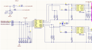
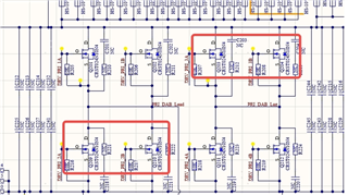
My customer used UCC21225A as functional isolation to eliminate the effect of ground bounce when hard switch off for their DAB topology.

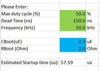
And they connect the OUT to UCC27624 to expand the drive current. they use boot strap supply for the high side UCC27624.

Recently, they report a issue that 1/1000 of the board report a issue that the high side waveform will lost during the machine start up. and they already located the issue to UCC21225A. 

due to the input PWM is good without output on UCC21225A.

Due to boot strap, I just let them check the VDDB-VSSB to see whether trip the UVLO. but it seems the power supply is about 12V and stable.
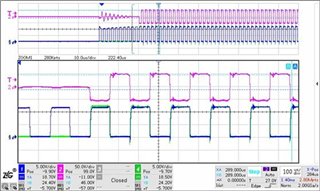
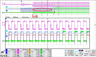
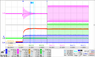
CH1:Q209_GS  

CH2:Pri DAB Lead - Pri DAB Lag

CH3:VDDB-VSSB    

CH4:Q203_GS

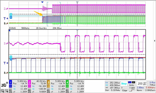
see CH4, high side Vgs PWM is lost.

And they also do the ABBA test, and found the issue followed the device. But from the waveform we can see it can recover so I don't think the device is broken.

Could you kindly tell me what next step to check?

BR

Emma

  • Hi Emma,

    Do they have any waveforms that show VDDA-VSSA? 

    Since the high side output PWM is being lost, it might be good to capture that channel's VDD waveform.

    And they also do the ABBA test, and found the issue followed the device. But from the waveform we can see it can recover so I don't think the device is broken.

    Could you provide a little more detail on this ABBA test?

    Looking forward to hearing back!

    Regards,

    Hiroki

  • Hiroki,

    Since the high side output PWM is being lost, it might be good to capture that channel's VDD waveform.

    No, you can check my schematic, actually, in this design OUPUT B is the high side channel.

    For the ABBA test, 

    they changed the suspicious device to good board and the waveform will be good.

     but change the good device to suspicious board, the waveform will emerge similar issue. However, the waveform will recovery later, so I can not tell it is a device broken.

    I also calculate their delay time, it should be about 60us after UVLO, it is aligned with their normal waveform.

    I also think about the noise on DISABLE PIN, and I let customer remove the C529 and connect DISABLE PIN to GND directly.

    still no improvement.

    In order to double check the VDDB supply issue, I have customer use external power supply on VDDB-VSSB, and the issue disappeared.

    But I don't know how to explain it, since the supply by bootstrap seems also enough and stable.

    BR

    Emma 

  • Hi Emma,

    I see, thank you for the clarification.

    It looks like the issue may not be with the UCC21225A device if the issue only appears on a specific board.

    Has the customer looked into the suspicious board to see what differences it has with the good one? If not, this would be a good next step to find the root cause of the issue. 

    Regards,

    Hiroki

  • Hiroki,

    SORRY, I found I make mistake on ABBA description.

    For the ABBA test, 

    they changed the suspicious device to good board and the waveform will emerge similar issue. However, the waveform will recovery later, so I can not tell it is a device broken.

    but change the good device to suspicious board, the waveform will be good.

    so the issue followed UCC21225A.

    BR

    Emma

  • Today I have customer try to extend the pre charge for boot capacitor, which means only send out low side FET drive signal. 

    originally it is 10 pulses, now extend to 20 pulse, and the issue disappeared. it seems that this device need more delay time.

    CH3 VDDB-VSSB

    CH4 OUTB

    But I know that Start up delay refers to the time from the activation of the driver to the first high-side output pulse. This includes the time it takes the bootstrap capacitor to reach the UVLO level, plus the VDDA Power-up Delay Time (t_(VDD+to OUT))of 50 us for UCC21520. 

    originally the delay is over 100us.

    I also check the output pin to GND with no obvious difference.it is test by multimeter under resistor mode.

    Good

    NG

    VDDB-VSSB

    1.57M

    1.6M

    VDDA-VSSA

    1.57M

    1.57M

    OUTB-VSSB

    1.67M

    1.75M

    OUTA-VSSA

    1.67M

    1.75M

    Could you kindly help me on further debug?

    BR

    Emma

  • Hi Emma,

    Thank you the clarification!

    Let me discuss with the team, as this is something that we have not seen previously. 

    I will get back to you by end of day tomorrow with a response.

    Thank you!

    Regards,

    Hiroki

  • Hi Emma,

    Saw that you continued the discussion via email.

    Closing the thread here to continue in email.

    Regards,

    Hiroki