This thread has been locked.
If you have a related question, please click the "Ask a related question" button in the top right corner. The newly created question will be automatically linked to this question.
Trying to figure out the issue I see with TPS65216D0 PMIC on several of the boards that came back as RMAs.
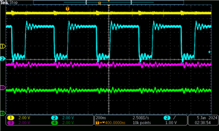
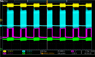
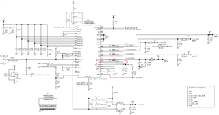
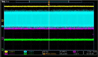
Attached are scoped snapshots of both known good and failed boards alone with excerpt of schematic. Pin 12=ch1, Pin13=ch2, Pin14=ch3, Pin15=ch4.
Hi Roman,
The device expert is out of office until Wednesday this week, but I will see if someone else on our team can try to provide some assistance today.
Best regards,
Matt
Hi Roman,
I only see two scope captures. The one on the left looks like a zoomed in version on the right side capture. Are these the captures from the failing board?
Where are the captures from the working board for reference?
Also how many boards are showing this issue? Are all the boards having a problem or some subset of your board count?
Regards,
James
Hi James,
The zoomed snapshot on the left side is of a known good board. Attached is the same 40us per division snapshot of known good board for comparison with the failed one on the right side.
Thank much.
Hi Roman,
Are there any schematic differences between the failing boards and the working boards?
Have you tried an A-B-A swap to see if the issue follows the board or the ICs?
Regards,
James
Hi James, there is no schematic difference between the failing and working boards. We found that once the PMIC is unsoldered off the board it is impossible to reuse it. Any other recommendations? Still wondering why PMIC on the working boards sees a flat static voltage on pin14 (pink) as shown on the left capture, unlike on failing boards looks like a pwm signal. Thanks.
Hi Roman,
We have moved ICs to different boards in the past without issues so it should be possible to move the IC from one board to the other without causing damage to the part itself. A-B-A swaps are fairly standard practice.
Right now you are describing an issue where an IC behaves differently on two identical boards so I don't have a clear answer for why that could be happening.
An A-B-A swap would narrow down the scope of the debug by a wide margin by confirming the issue source at a top level.
Another debug step would be to share a full register dump from the failing unit so we can look for fault / interrupt flags in R01, R02, and R07
Regards,
James
Hi James, what would be the easiest way to access those read registers and what is the exact info to look for? Thanks much
Hi Roman,
I agree with James that an A-B-A swap is a critical step to debug this. The top markings on the devices are production lot trace codes, so these do not indicate different revisions of the device. The devices are the same revision, just manufactured in different years. The A-B-A swap will quickly determine whether there is in fact some difference in the devices (which we would not expect) or a difference in the boards which you have indicated should be the same.
Regards,
Matt
Hi Roman,
From your schematic it looks like you already have your I2C lines hooked up to a host. You will need a valid 1.8V or 3.3V pull-up on the SCL / SDA lines and you need some kind of I2C communication interface to talk to the PMIC.
There are three states where the PMIC allows I2C communication: WAIT_PWR_EN, ACTIVE, and SUSPEND
The issue I see here is that if you are constantly resetting due to a power fault on DCDC4, I'm not sure if I2C access is available consistently. You may have to target a window of time where I2C communication is available.
If you don't have a way to use I2C communication, you might consider using our BOOSTXL-TPS65218 socket board to interrogate the chip using a micro-USB cable and the IPG-UI software.
It may be easier to start by swapping out the DCDC4 inductor or disconnecting any output connections if possible. If the boards are the same on a schematic level, there could be an issue with one of the components (solder disjoint or seating issue) or there could be an issue with an externally connected device.
Regards,
James
Hi Roman,
Also what is the max voltage / current reached on the DCDC4 output for the failing board?
Regards,
James