Hi
I am using a document SLUP263 which is produced by Texas Instruments for designing a LLC based Power Converter.
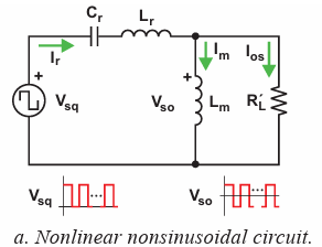
With this documents, I have designed my FULL BRIDGE Resonant Power Converter. There is an example written in this document. Following the same path, I have calculated the Resonant capacitor Cr, Resonant Inductor Lr and Magnetizing Inductance Lm values as given below.

By using this formula,
The Converter is designed for Load RL= 5.6 ohm, Vin = 60V, Vout = 30, Transformer turns ratio = 2, full bridge inverter, full bridge rectifier using diodes, Switching Freq F= 120Khz . I started my calculation based on above formulas prescribed in the documents.
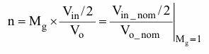
Turns ratio: n = Vin (full bridge inverter) / Vout = 60 / 30 = 2;
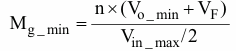
Mg_min = [2 * { 30 * (1-1%) + 0.3}] / [{75}-Full bridge] = 0.8
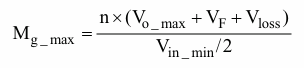
Mg_max = [2 * { 30 * (1+1%) + 0.3 + 0.5}] / [{45}-Full bridge] = 1.4
Qe= 0.45 and Ln = 3.5 are extracted by through Matlab Qe, Ln vs switching freq F graphs.
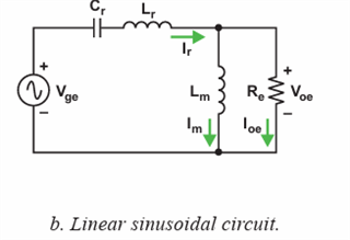
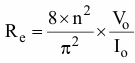
Re = { 8n2 / pi2 } * RL(5.6ohm) = 18.1ohm
therefore,
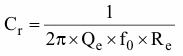
Cr = 1 / {2 * pi * Qe * F * Re} = 162nF
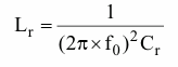
Lr = 1 / {2 * pi * F }2 * Cr} = 10.8uH
Lm = Ln * Lr = 3.5 * 10.8v = 38uH
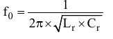
Fr = 1 / {2 * pi * √ Lr * √Cr } * Cr} = 120 Khz .. Resonant Freq Fr
The above values are calculated values.
The Problem is when I bought the nearest values for the hardware like Cr =150n, Lr= 10uH & Lm = 39uH, the test or the below measurment results between Frequency F vs Vout shows that the resonant freq F is somewhere in between 25-55KHz which is not matched with resonant frequency Fr calculated in the above calculations. Please suggest how can i move the resonant frequency to 120Khz, Also which values of Lr, Cr & Lm are required if the above-calculated values are incorrect. I have tested my LLC hardware with different loads like RL = 10, 5.6 ohm, 50 ohms, 125 ohms. but in all cases the resonant freq F in calculation is not matched when comparing with measurment results to find the resonant Frequency F.
Frequency F Vin RL = (5.6)->6ohm Vout ILoad Pin Pout Efficiency * 100
| 55 | 60 | 6 | 3.5 | 4.176 | 33.2 | 14.616 | 0.440241 |
| 60 | 60 | 6 | 3 | 3.2784 | 22.17 | 9.8352 | 0.443627 |
| 65 | 60 | 6 | 2.7 | 2.7142 | 16.5 | 7.32834 | 0.444142 |
| 70 | 60 | 6 | 2.5 | 2.3342 | 13.11 | 5.8355 | 0.445118 |
| 75 | 60 | 6 | 2.3 | 2.0561 | 10.95 | 4.72903 | 0.431875 |
| 80 | 60 | 6 | 2.2 | 1.8402 | 9.2 | 4.04844 | 0.440048 |
| 85 | 60 | 6 | 2.1 | 1.6708 | 8.15 | 3.50868 | 0.430513 |
| 90 | 60 | 6 | 2 | 1.5326 | 7.29 | 3.0652 | 0.420466 |
| 95 | 60 | 6 | 1.9 | 1.417 | 6.6 | 2.6923 | 0.407924 |
| 100 | 60 | 6 | 1.8 | 1.3203 | 6.06 | 2.37654 | 0.392168 |
| 105 | 60 | 6 | 1.8 | 1.2357 | 5.61 | 2.22426 | 0.396481 |
| 110 | 60 | 6 | 1.7 | 1.1634 | 5.25 | 1.97778 | 0.37672 |
| 115 | 60 | 6 | 1.7 | 1.0984 | 4.92 | 1.86728 | 0.379528 |
| 120 | 60 | 6 | 1.7 | 1.0421 | 4.6 | 1.77157 | 0.385124 |
| 125 | 60 | 6 | 1.6 | 0.9912 | 4.41 | 1.58592 | 0.359619 |
| 130 | 60 | 6 | 1.6 | 0.9452 | 4.14 | 1.51232 | 0.365295 |
| 135 | 60 | 6 | 1.6 | 0.9025 | 4.05 | 1.444 | 0.356543 |
| 140 | 60 | 6 | 1.5 | 0.8643 | 3.9 | 1.29645 | 0.332423 |
| 145 | 60 | 6 | 1.5 | 0.8305 | 3.78 | 1.24575 | 0.329563 |
| 150 | 60 | 6 | 1.5 | 0.7995 | 3.66 | 1.19925 | 0.327664 |
| 155 | 60 | 6 | 1.5 | 0.7685 | 3.4 | 1.15275 | 0.339044 |
| 160 | 60 | 6 | 1.4 | 0.7355 | 3.39 | 1.0297 | 0.303746 |
| 165 | 60 | 6 | 1.4 | 0.7167 | 3.36 | 1.00338 | 0.298625 |
| 5 | 60 | 6 | 1.4 | 1.1846 | 5.5 | 1.65844 | 0.301535 |
| 10 | 60 | 6 | 2.4 | 2.0274 | 10.5 | 4.86576 | 0.463406 |
| 12 | 60 | 6 | 3.4 | 3.92 | 29 | 13.328 | 0.459586 |
| 15 | 60 | 6 | 3.1 | 3.2167 | 21.8 | 9.97177 | 0.457421 |
| 20 | 60 | 6 | 2.5 | 2.2607 | 12.26 | 5.65175 | 0.460991 |
| 25 | 60 | 6 | 3 | 3.1903 | 20.44 | 9.5709 | 0.468244 |
| 30 | 60 | 6 | Burned* |
Note * Burned = Lr is burned due to high current because of higher Mg.
Frequency Vin RL = 50ohm Vout ILoad Pin Pout Efficiency * 100
| 55 | 60 | 50 | 29.3 | 0.599 | 19.3 | 17.5507 | 0.909363 |
| 60 | 60 | 50 | 28.4 | 0.5989 | 18.78 | 17.00876 | 0.905685 |
| 65 | 60 | 50 | 27.4 | 0.5987 | 18.18 | 16.40438 | 0.902331 |
| 70 | 60 | 50 | 26.5 | 0.5987 | 17.7 | 15.86555 | 0.896359 |
| 75 | 60 | 50 | 25.7 | 0.5988 | 17.28 | 15.38916 | 0.890576 |
| 80 | 60 | 50 | 24.9 | 0.5987 | 16.89 | 14.90763 | 0.882631 |
| 85 | 60 | 50 | 24.2 | 0.599 | 16.38 | 14.4958 | 0.884969 |
| 90 | 60 | 50 | 23.5 | 0.5989 | 16.02 | 14.07415 | 0.878536 |
| 95 | 60 | 50 | 22.9 | 0.5989 | 15.69 | 13.71481 | 0.874112 |
| 100 | 60 | 50 | 22.3 | 0.5989 | 15.4 | 13.35547 | 0.867238 |
| 105 | 60 | 50 | 21.5 | 0.5993 | 14.8 | 12.88495 | 0.870605 |
| 110 | 60 | 50 | 20.8 | 0.5984 | 14.55 | 12.44672 | 0.855445 |
| 115 | 60 | 50 | 20.2 | 0.5975 | 14.2 | 12.0695 | 0.849965 |
| 120 | 60 | 50 | 19.5 | 0.5987 | 13.83 | 11.67465 | 0.844154 |
| 125 | 60 | 50 | 18.9 | 0.5988 | 13.47 | 11.31732 | 0.840187 |
| 130 | 60 | 50 | 18.2 | 0.5987 | 13.1 | 10.89634 | 0.831782 |
| 135 | 60 | 50 | 17.4 | 0.5987 | 12.72 | 10.41738 | 0.818976 |
| 140 | 60 | 50 | 16.6 | 0.5988 | 12.16 | 9.94008 | 0.817441 |
| 145 | 60 | 50 | 15.8 | 0.5986 | 11.82 | 9.45788 | 0.800159 |
| 150 | 60 | 50 | 15 | 0.5988 | 11.28 | 8.982 | 0.796277 |
| 155 | 60 | 50 | 14.1 | 0.5989 | 10.8 | 8.44449 | 0.781897 |
| 160 | 60 | 50 | 13.2 | 0.5989 | 10.26 | 7.90548 | 0.770515 |
| 165 | 60 | 50 | 12.2 | 0.5988 | 9.72 | 7.30536 | 0.75158 |
| 5 | 60 | 50 | 8.8 | 0.5988 | 7.08 | 5.26944 | 0.744271 |
| 10 | 60 | 50 | 18.1 | 0.5989 | 12.66 | 10.84009 | 0.856247 |
| 12 | 60 | 50 | 23.7 | 0.5989 | 16.2 | 14.19393 | 0.876169 |
| 13 | 60 | 50 | 29.7 | 0.5989 | 20.22 | 17.78733 | 0.87969 |
Please suggest this issue.
Kind Regards
Arsalan