This thread has been locked.

If you have a related question, please click the "Ask a related question" button in the top right corner. The newly created question will be automatically linked to this question.

UCC28951-Q1: Support on UCC28951-Q1 controller

Part Number: UCC28951-Q1
Other Parts Discussed in Thread: UCC28951, UCC28950, UCC28950EVM-442

Hi Team,


Good day!

I would like to know if I can use the UCC28951-Q1 PSFB controller for (5-8kW) applications. I have a wide input range up to 800V DC. Output is LVDC.


If yes, could you provide me with any efficiency reports you have at this power range for UCC28951-Q1?

If it does not support this high output power, could you suggest to me some full bridge controllers that support the power range?


Thank you in advance. Hoping to hear from you soon.

  • Hello,

    What is the minimum input range of your design?  Typically PSFB are designed for a 3 to 1 input range.

    The UCC28951 is similar to the UCC28950.  Parametrically they are identical.  The only difference was the UCC28951 was designed for duty cycles above 90%.

    The following link will bring you to a 600 W evaluation module using the user's guide, with performance test data for you to evaluate. 

    https://www.ti.com/tool/UCC27714EVM-551

    The next link will bring you to an application note discussing the differences between the UCC28950 and UCC28951. 

    https://www.ti.com/lit/pdf/slua853

    Regards,

  • Hi Mike,

    Thanks for the quick response.

    Input range is from 400V to 800V DC. 

    I am currently evaluating the 600 W design on Pspice for TI. TI Webench tool shows the UCC28951-Q1 based design for 4.32kW @24V DC output. 

    But I am facing issues in replicating the same power in Pspice for TI. Hence my concern about the controller's design limitations.

    Some clarifications on this aspect would help me.

    Thank you.

  • Hello,

    A phase shifted full bridge controller is a good choice for this application.  A 2 to 1 input range is O.K.  The controller itself does not limit the power it can be design for.  This is based on the components you select for your design and your thermal management design. 

    The following link will bring you to an application that reviews how to design with the UCC28951 in a phase shifted full bridge.  It goes through the step by step design process.  There is also an excel design tool that goes along with this application note and there is link to it inside the tool.

    https://www.ti.com/lit/pdf/slua560

    Regards,

  • Hi Mike,

    I have two queries on the application document you have provided to refer.

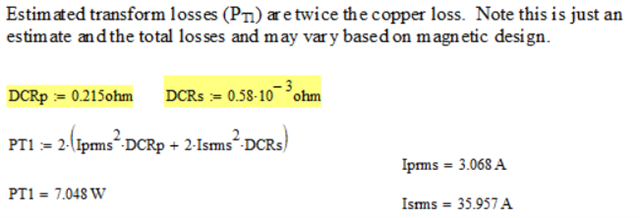
    1)I was going through the application document and at section 4, the Estimated transformer loss given in the document is heavily deviated from the calculations I did for the same Mathcad. Please provide your thoughts on the same.

    The above snips shows my calculation vs the application document calculation.

    2) In section 12, the output transfer function (GCO(f)) gives complex outputs. As a result, the Rf resistor value is in complex form in my calculation. In the application document Rf values is  27.9 kΩ. Kindly comment on this as well. It would be great if you can provide how the calculations have been done.

    Thank you. Hoping to hear from you soon.

    Alen

  • Hello,

    Your inquiry has been received and is under review.

    Regards,

  • Hello,

    1. The Math in the application note for estimating the transformer loss is based on 50% coming from conduction loss and 50% coming from core loss.  The math is correct.  However, I believe there is a typo in the DCRs of the primary and secondary of the transformer.  

    The secondary DCR should be 0.58 mOhms and not 0.58 ohms.

    2.  It should be a complex number and you need to take the magnitude of it for the calculations for setting the Rs and Cs.  There is an excel file that goes along with this application note that will calculate the Rs and Cs for you.   

    There is also a MathCAD file with the same equations that you can use at the following link.

    https://dr-download.ti.com/design-tools-simulation/calculation-tool/MD-Wr38lMfWTI/01.00.00.0D/sluc210d.zip

    Regards,

  • Hi Mike,

    I am still facing issues with design.

    The values I calculated using the design document equations and the design calculator sheet does not match. Nevertheless I've simulated the design using both the values in Pspice for TI. Even thou the design is for 24V, I am observing 12V at the output(for both the calculations done manually and the calculator results).

    I am attaching the calculator sheet with all the parameters I used for the design. Kindly review it and provide your thoughts on how to proceed.

    Thank you in advance.

    Alen

    2046.SLUC222D.xls 

  • Hello,

    Your inquiry has been received and is under review.

    Regards,

  • Hello,

    The UCC28950EVM-442 was designed with the application note previously referenced.

    Many engineers have used the application note and excel tool to design PSFB converters and have had good luck.  Sorry that you are finding issues with it.

    Which other equations do not agree with the app note?

    In your simulation if you are not getting the correct output voltage your transformer turns ratio could be off.  I would suggest double checking it.

    Regards,

  • Hi Mike,

    I have double checked the transformer turns ratio. I am observing 21:1 and have simulated with the same. Even tried 11:1 just to observe some change, I am still observing 12V for both the turns ratio. 

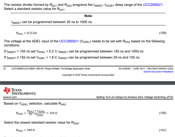
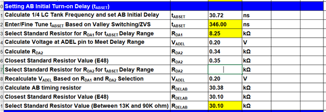
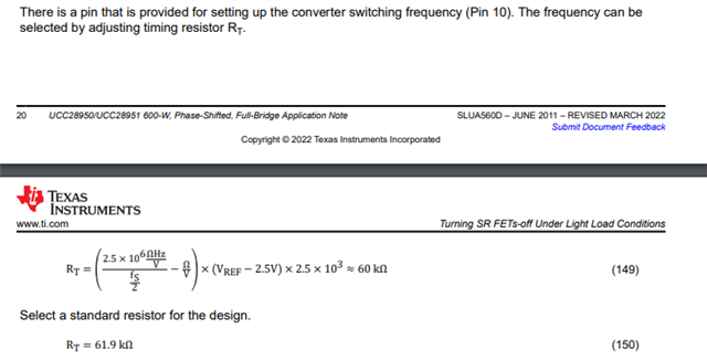
    Almost all the values calculated from the application note and the excel sheet have around 1-5% variation. Some values which are completely different are Rda2, Rdelab, Rdelcd, Rdelef and Rt. Rt is the timing resistor and the calculated value is 300k and the excel sheet value is 121k for the same 100kHz frequency.

    Can I have a working session with any of the application engineers? How can I get in contact for the same? 

    Thanks and Regards,

    Alen

  • Hello Allen,

    I helped a customer trouble shoot an issue with load regulation in there simulation last week.  The issue that customer was having is the primary of the transformer was not seeing the voltage it should be.  For some reason the current sense transformer was causing a drop.

    Could you check the voltage across the transformer in your simulation to see if it it is getting the voltage across the primary that it should.  If not one of the components is causing a voltage drop that you will need to remove. 

    With the transformer issue it was in a tina model.  It was resolved by changing the current sense transformer with a current controlled current source.  Please check the transformer first before making any adjustments.

    Another customer made there shim inductor too big.  Not saying this is your issue.  You just need to trouble shoot your simulation like it is a real circuit and find out why the output voltage is not climbing up to what it should be.

    I will take a look at the excel tool to see what is up with those values.  

    Regards,

  • Hello,

    I checked the excel design tool vs the application note in regards to Rda2, Rdelab, Rdelcd, Rdelef and RT.

    https://www.ti.com/lit/an/slua560d

    https://dr-download.ti.com/design-tools-simulation/calculation-tool/MD-rlvLC7vkDZ/01.00.00.0D/sluc222d.zip

    I checked the excel tool and the values for Rda2 match the application note.

    Resistor Rdelab and Rdelcd app note and tool matched as well.

    Resistor RT matched the app note and excel tool as well.

    Regards,

  • Hi Mike,

    Thanks for your inputs. 

    I have managed to get 24V output for my design. But the time taken to achieve the stable output  is about 100ms in steady state analysis. 

    Why would that be? 

    In steady state analysis, the steady state output should come right away.

    I am not sure if the soft start has been modelled to the steady state analysis in Pspice for TI, but if so, the calculated soft start is around 15ms. But that does not explain the 100ms time for steady state.

    Waiting for your inputs.

    Thanks in advance,

    Alen

  • Hello,

    Your inquiry is under review and I will get back to you shortly.

    Regards.

  • Hello,

    You might want to set the initial voltages to the output capacitor close to the controlled output voltage; as well as, the initial DC current through the output inductor to the load current.  This should help speed up the simulation.

    Regards,

  • Hello Mike,

    The design I am working on is 5kW but the simulation doesn't seems to support that much. Any output load that takes more than 1kW, the output voltage is dropping. Why would that be? 

    The MOSFETs that have been used on both sides are rated fine. I am not understanding what might be limiting the current.

    Kindly advice.

    Thanks,

    Alen

  • Hello,

    Your inquiry is being evaluated and I will get back to you shortly.

    Regards,

  • Hello,

    I am thinking that your CS transformer and CS resistor may not be setup correctly if the output is dropping out as the load increases.

    You might want to study the CS signal, Comp, voltage across the primary and output voltage as you change the load in your simulation.  The CS is cycled by cycle current limited at 2 V.  Your issue just might be the CS resistor is too large.  

    If you don't find an issue there the other think might want to check is your slope compensation to make sure it is not limiting your duty cycle.

    Regards,

  • Hi Mike,

    I have rectified the issue with CS signal, as the value was coming more than 2V. I did not find any issue with the slope compensation so far.

    Still the design is not giving 24V output at 4kw or 5kw. 

    I am using both the excel design tool and the 600W design document, but still I find some dissimilarities between them and the simulation.

    For ex, the Rt resistor value for 200kHz switching is 60k in excel tool and 150k if using the equation in the design document. Nevertheless, both the values in simulation does not correspond to 200kHz switching. 60k Rt shows a 100kHz switching and the 150k Rt shows somewhere less than 50kHz in simulation.

    Since I am doing the design with 200kHz, I have given Rt as 30k and it is switching properly in the simulation. But still unable to achieve the output.

    Can I have a working session with any of the application engineers for a hands on support?

    Kindly let me know your thoughts.

    Regards,

    Alen

  • Hello,

    The excel design tool was developed in 2010 and has proven reliable in designing phase shifted full bridge controllers.  So if your simulation schematic matches the excel tool that is a good start.

    Your next step is debug the simulation.  If you are not getting the desire output voltage something is not right your design or something modeled is not doing what it is supposed.

    1.) Check your transformer turns ratio make sure it works over you input range.

    2.) Check your feedback and make sure your DC output is set correctly.

    3.) Check your current sensing to make sure that is correct.

    4.) Probe the circuit and look for things that are not behaving the way they should.

    Regards,

  • Hi Mike,

    I have managed to get the desired 24V @4 -7kW, but through diode conduction. The  synchronous rectifiers have been turned OFF for this. With the SR FETs(OUTE & OUTF) turned ON, the design is still failing. Diode conduction on higher loads will have immense losses. 

    Do you have any idea why the design works without SR FETs and not with them? 

    Is there any way to control the SR FETs switching?

    Kindly provide your thoughts at the earliest.

    Thanks,

    Alen

  • Hello,

    The design should work with SR FETs.  Double check to make sure that the out E and out F are controlling the correct SRs?  If they are not you might just be shorting the transformer with the SRs.  The following link will bring you to 600 W PSFB design using the UCC28950.  Please not this design also works with the UCC28951.  You can use this design as a reference to double check your SR connections.

    https://www.ti.com/lit/pdf/sluu421

    The other thing you can do is to load the design with 10% and evaluate the current through the SRs and setup the delay timing at this light load as well.

    Once you are convinced the timing is setup correctly then you could gradually increase the load and monitor the Vds voltage of the SRs, current through the SRs and voltage across the SRs to make sure everything is functioning correctly.

    Regards,