Other Parts Discussed in Thread: LM25145, LM5143, LM25148
Hello,
We are designing a multibay charger and would like to use the LM5148 due to the CC control mode for charging batteries.
We need applications help to understand how to configure the circuit.
Design specifications:
- Vin 36Vin nominal
- Vout 3 - 26V
- Iout 0 - 18A
- Switching Freq 250kHz
- Planning to use a current sense resistor in the 1.5 – 1.8 mOhm range.
- Need to support pre-bias start up.
- 2 DC/DC could be operated in parallel to double the output current
Questions:
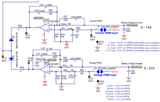
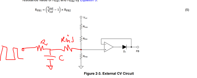
- How would be interface external op amp to control both voltage and current similar to LM25145 design (attached)?
- Should the FB pin be grounded and use the COMP pin?
- During standby mode, we would like to disable the Buck converter and hence would use EN pin to enable/disable the converter from external MCU. When we pull the EN pin low to disable the converter, do we lost the VCC 5V internal regulated supply as well or its independent ? We would like to use this 5V supply to power our CC/CV opamps.
- Any concerns with pre-bias start up turning converter on/off repetitively with battery attached.
- Since we may or may not be using FB pin for external CC/CV control, can we still use PG/SYNCOUT pin to implement 180 phase shift between the 2 buck converters ?
-
Does PG has to be high (FB pin volage within specified range) to able to enable SYNCOUT clock pulse?
Thank you, Keith