Other Parts Discussed in Thread: , BQ25751
Hi,
To test TPS25751's Source Role, we used some mobile phone such as iPhone, Huawei Honor, and so on. It seemed TPS25751 could NOT be compatible with some of them, some issue happened. Could you kindly help to analyze?
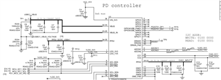
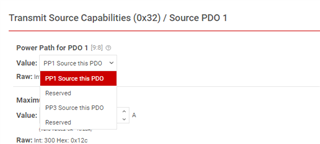
In addition, the related TPS25751 registers' data was read as following,
(1)When I2C INT was detected by MCU, delay around 500ms;
(2)Read 0x03, 0x14, 0x1A, 0x3F, 0x40, 0x34, 0x35 Register;
(3)Clear the I2C INT by writing all 1 to 0x18;
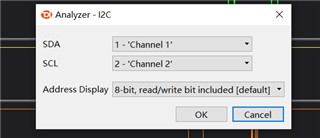
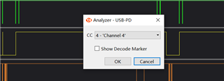
The related I2C data was attached as following:
20240314_TPS25751_I2C_RegisterCapture.zip
(Note: You can download the software to view the files:
)
1.iPhone15 Promax
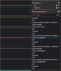
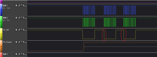
It seemed the first try to establish PD contract was valid, but then a PD Hardreset occured. And it repeated this process, and could not establish stable charging process.
2.Huawei Honor
Same as the above iPhone.
3.Xiaomi Redmi K40
Same issue, but after this issue the charging process was stable.