This thread has been locked.

If you have a related question, please click the "Ask a related question" button in the top right corner. The newly created question will be automatically linked to this question.

BQ25616: NA

Part Number: BQ25616

Dear ,

       bq25616 can't stop charge current at 45 degree (charging current don't change to 0mA and status pin don't change to charging complete ) 

       VBAT have change from 4.2V to 4.1V meeting JEITA.

       Charge current setting is 1.2A .

      Please let us know your comment ..thank 


  • Hello,

    Can you confirm if you are using BQ25616 or BQ25616J?

    Regards,

    Mike Emanuel

  • Dear ,

    used the BQ25616J

    Good day

  • Hello Michael,

    This is FAE Dave, and Rence is my customer at industrial PC sector.

    First, please see the battery info here:

    They've guessed that if it's the internal protection from battery to limit the current input.

    However, the battery vendor replied that the battery won't limit the current.

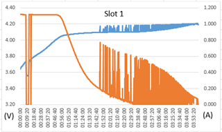
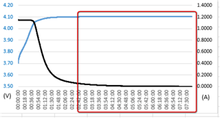
    Here's the V-I curve, starting from ambient of 40 degree C, you can see that there is the instant high current and low after 1:51 till battery is fully-charged.

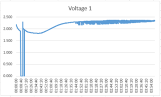
    At first, they are guessing the temperature being too high to reach JEITA's VT3, and they test the VTS. Please see the figure below:

     z

    They found that when current is at sudden large value, TS voltage is higher than when it just started.

    What could result in the REGN voltage being changed? Is it related to the current being suddenly increased and decreased?

    What is the possible reason here? Thanks for the explanation.

    Best Regards,
    Dave

  • Hello Rence and Dave,

    On BQ25616J termination is disabled at temperatures above VT3.

    When VBUS is less than 6V, VREGN follows VBUS with the difference of the dropout voltage. A changing input voltage will change the REGN voltage if less than 6 V. The TS voltage percentage will remain the same, however the TS voltage itself may change because REGN changes.

    Regards,

    Mike Emanuel

  • Dear Mike,

             kindly you please let us know what charge current can't change to 0mA when charge current below 0.1C (>30 mins)

              Test setting as below list 

              1) ambient temp is 45C

              2) Vset is 4.2V  , Charge current is 1.125A

              3) when I charge below <100mA over 1hour as below table(3:40:30 to 5:11:40....) ...


  • Hi Rence,

    As stated in the last post, termination is disabled at temperatures above VT3. If you want to terminate lower the temperature to between VT2 and VT3. This is intrinsic to the behavior of the part.

    Regards,

    Mike Emanuel

  • Hello Michael,

    Thanks for the explanation here.

    I have another two questions.

    Based on the description, will the top-off timer be reset when the temperature across T3?

    When temperature is above T3, the termination is disabled, then when it's at the top-off timer phase, it should be reset, is it correct?

    Another question is:

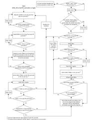
    Do we have the charging flow diagram? (I show the PD controller one here, do we have similar diagram for charger?)

    Thanks for the reply.

    Best Regards,
    Dave

  • Hi Dave,

    Because there is no termination there will not be a top-off timer.

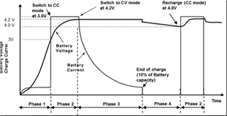
    Please see Figure 9-5 for battery charge profile. Please keep in mind that also because this part is standalone there is no top-off timer. Termination will occur when for the device when , "the battery voltage is above the recharge threshold, and the current is below termination current."

    Regards,

    Mike Emanuel

  • Hello Michael,

    The system problem we occur is that when testing the charger, the charge termination is occurred at about 3 hours. But at the 40 degree C ambient, there will be the 3-4 hours difference for this timing (STAT=HIGH), we need to find some reason and we suspect it's related to JEITA, thus we have the problems here.

    Please let me summarize our problems:

    About JEITA:

    1. Based on the JEITA profile, at the high temperature (above T3), the voltage will be decreased to 4.1V. It will not show the STAT high, is it correct?

    2. Any timer event is not available at BQ25616J? Is it correct? Top-off timer and safety timer part? There are a lot of paragraphs talking about timers in datasheet. Please help to confirm, and our customer is willing to know whether the timer will be reset at JEITA T3. If timer is not present, then there will be no meaning for the time-out issue.

    About charge flow:

    Do we have exact flow of charging during different phase?

    We would like to know these flows:

    1. Room temperature (<T3)

    2. High temperature (>T3)

    3. Room > High > Room

    Thanks for the support.

    Best Regards,
    Dave

  • Hello Dave,

    1. I have confirmed when above T3 with proper input applied that the STAT pin is low. Is this what you are seeing? In addition, you are correct the regulation voltage is 4.1 V above T3. Can you monitor the TS voltage and REGN voltage when this is happening? I wonder if you are on the edge of VT3. You may be entering JEITA with higher charge current, but as the charge current (and battery temperature) lowers you re-enter normal NTC range.

    2. Please see Section 9.3.7.5 Charging Safety Timer. The safety timer is active. In this section it says, "During faults of BAT_FAULT, NTC_FAULT that lead to charging suspend, the safety timer is suspended as well. Once the fault goes away, the timer resumes. If the user stops the current charging cycle, and starts it again, the timer gets reset (toggle of CE pin)."

    Can you please rephrase your question about charge flow? Please refer to Figure 9-6 for BQ25616J JEITA profile.

    Regards,

    Mike Emanuel

  • Hello Michael,

    Thanks for your reply.

    We have another problem here.

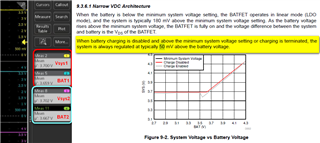
    At Charge mode, our customer found Vsys1/2 vs. BAT1/2 difference at about 50mV.

    Is this within the spec.?

    For charge flow, it means the charging tree diagram that be related to the figure I attached.

    Best Regards,
    Dave

  • Hi Dave,

    Please explain the condition where difference between VSYS and VBAT was at 50 mV. Was this in charging, discharging, etc.? If it is the condition listed here in yellow, typical 50 mV is in alignment with the reported 50 mV. 

    We do not have an explicit tree diagram, but please follow the POR sequence from Section 9.3.1 to 9.3.3.6. Also take a look at the battery charging profile in Figure 9-5.

    Regards,

    Mike Emanuel

  • Hello Michael,

    Thanks!

    It's at charging phase, thus the 50mV should not align. (Should be 180mV typically.)

    Best Regards,
    Dave

  • Hi Dave,

    This is not the phase mentioned in Section 9.3.6.1, "When battery charging is disabled and above the minimum system voltage setting or charging is terminated, the system is always regulated at typically 50 mV above the battery voltage." The quoted phase is not charging with above MINSYS or charging terminated.

    The reported phase is the charging phase. During charging, the BATFET is typical 19.5 mOhm. At 2 A charging current the difference between VSYS and VBAT is typical 39 mV.

    Regards,

    Mike Emanuel