Other Parts Discussed in Thread: TPS54160, TPS54160A
Dear TI team of experts.
We have an unexpected behaviour in the series production of one of our PCBs. After some time, the output voltage of the two DC/DC converters starts to oscillate.
This phenomenon did not occur with the pilot series, which is identical to the series produced.
We implemented the DC/DC converters according to webench.
Only with the TPS63000 did we not implement the Cff in parallel with the R107. However, this has already been tested without improvement.
Another point that deviates from the data sheet is the RC filter between VIN and VINA of the TPS63000.
The unstable output signal triggers a brown-out in the processors.
If the PCBs are operated with 32V, we have not seen this phenomenon occur.
Our customer has a system voltage of 41V, which is what U100 was designed for. In the test case, U100 only has one LED and the U101 as a load.
Is there an obvious error or a tip on how we can get the behavior under control?
We are grateful for all support.
Best Regards
Fabio
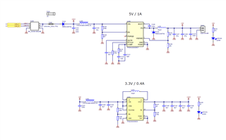
Schematic:
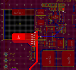
Layout U100 / TPS54160
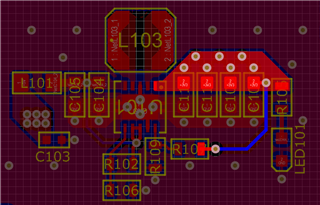
Layout U101 / TPS63000
3V3 Stable:
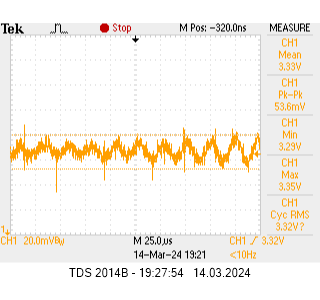
3V3 Instable: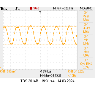
5V Stable:
5V Instable:
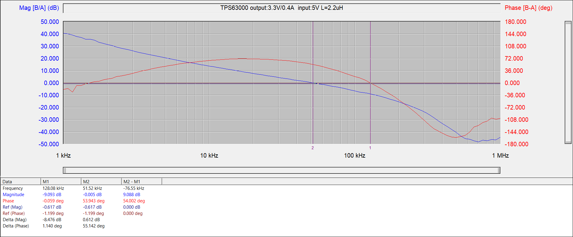
Webench Exports:
tps54160a_Vout_5V.pdftps63000_Vout_3V3_Webench.pdf