- Ask a related questionWhat is a related question?A related question is a question created from another question. When the related question is created, it will be automatically linked to the original question.
Original question:

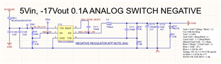
TPS54202H: Schematic check for 5V to -17V inverting buck converter
Hello,
Built boards with the circuit in the linked forum post.
However, I'm not seeing any output voltage. It's supposed to be -14.6V. We disconnected any output circuitry to isolate the issue. EN pin (pin 5) is 1.300mV, and VIN (pin 3) is 5V. I probed the SW signal (pin 2) and am not seeing any oscillations.
The EN pin is going through a voltage divider of 22k over 7.63k with the top attached to 5V and bottom attached to the -17V rail. So it should be 5.66V above the -17V rail, well within the 7Vmax,EN.
Inductor is 56uH, and feedback network is 47k over 2k with 100pF (compensation as per Webench) from Vfb to the output of the inductor (GND).
Thanks,
Derek