This thread has been locked.

If you have a related question, please click the "Ask a related question" button in the top right corner. The newly created question will be automatically linked to this question.

TPS25750: Power management forum

Part Number: TPS25750
Other Parts Discussed in Thread: BQ25713B, BQ25792, TPS25751, BQ25713, TPS25730, BQ25731

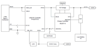
Please tell me about the compatibility of TPS25750 and BQ25713B.

When I referred to the product information for TPS25750, I was advised to consider BQ25792 as the battery charger IC to be combined with it.
I was considering using BQ25713B for the project I am developing, but does this mean that BQ25713B is not suitable?
I am concerned about the product information, so please let me know about the compatibility of the above.

  • Hi Takashi, 

    Thank you for reaching out!

    Please see the following E2E on our new device, the TPS25751 and the battery chargers supported: https://e2e.ti.com/support/power-management-group/power-management/f/power-management-forum/1346998/faq-tps25751-migrating-from-the-tps25750-to-the-tps25751

    The TPS25751 is compatible with the BQ25713, not BQ25713B

    Please let me know if you have additional questions/concerns. 

    Best Regards, 

    Aya Khedr 

  • Dear Aya Khedr
    We become indebted to.
    Your valuable guidance allows us to avoid known problems in advance.
    Thank you very much.
    If possible, please let me know the following.
    The product we are planning to develop will receive power from the PD and will not supply power to the other side.
    In this case, is it okay to leave the VBUS terminal of the TPS25751 open?
    We apologize for the inconvenience, but please continue to let us know.

  • Dear Aya Khedr

    I am considering changing to the TPS25751 you mentioned, but when I looked at this product page, it was listed as not yet in mass production.
    Could you please tell me exactly what kind of problem is the "known problem" that existed in TPS25750?

  • Hi Takashi, 

    No problem!

    Could you please share a high-level block diagram of your application? From my understanding, this is a sink-only application?

    The TPS25751 is recommended for all new projects and is expected to RTM within the next week or two. 

    Best Regards, 

    Aya Khedr 

  • Dear Aya Khedr

    Thank you for your reply.
    This development project is a sink-only application. However, since a charging circuit for the lithium polymer rechargeable battery is required, a control IC that can be connected to the BQ series is required.
    For sink-only applications, the TPS25730 can be considered, but while this IC is good for applications that use dry batteries, it cannot be used for applications that use rechargeable batteries.
    As you say, if TPS25751 is released soon, it can be used for this application.

    Bery Thank you !

  • Dear Aya Khedr

    Attached is a diagram of the configuration of the application under consideration.

    Although it is a sink-only application, the TPS25751D needs to supply 5V to the PP5V pin for internal LDO circuit and CC control. Also, I understand that the VBUS terminal needs to be connected to the VBUS_IN terminal because of the internal LDO circuit, but is this understanding of mine correct?

    Another thing I don't understand is the 5V current capacity to supply to the PP5V pin in this application.
    As mentioned above, this application is only a sink, so I think that the power consumed by 5V is about the sum of the power consumed by the TPS25751D and the power for CC control, but this idea is correct. Will it be?

  • Hi Takashi, 

    Your block diagram looks good! You may also refer to this reference design using the TPS25750+BQ25731 (should be similar to TPS25751+BQ25713).

    I will look into the other inquiries and get back to you by Wednesday. 

    Best Regards, 

    Aya Khedr 

  • Hi Takashi, 

    Apologies for the delay here. 

    1. The TPS25751 uses the PP5V power path to source 5V to VBUS and as a supply for the CCy pins as VCONN. It is not needed when pairing the device with a battery charger in a sinking application since the 5V will be supplied through PPHV. 

    2. VBUS_IN is the 5V-20V input which VBUS is the output (see block diagram below)

    3. 

    As mentioned above, this application is only a sink, so I think that the power consumed by 5V is about the sum of the power consumed by the TPS25751D and the power for CC control, but this idea is correct. Will it be?

    Typically, VCONN is provided by the source to power cables with electronics in the plug. This will most likely not be used in your application. 

    Please let me know if you have additional questions/concerns. 

    Best Regards, 

    Aya Khedr 

  • Dear Aya Khedr
    Thank you for your reply.
    One more thing, I don't really understand how to use the terminals of TPS25751D, so please let me know.
    I have attached a schematic diagram of the applied equipment that we are currently developing.
    Applied equipment is for use only in the sink.
    In this case, is it okay to leave the TPS25751D's VBUS terminal open and not connect it to anything as shown in the figure?
    Also, when using it as a sink only, how much current should I consider flowing into the PP5V terminal?Connection method when using TPS25751D

    We apologize for the inconvenience, but thank you for your understanding.

  • Dear Aya Khedr
    If you look at Figure 8-11. Power Supplies in the TPS25751D data sheet, the power supply for the internal operational amplifier is depicted as being supplied from the VBUS pin.
    If so, does this mean that if VBUS is left open, power will no longer be supplied to the internal operational amplifier?
    If so, should I connect it to VBUS_IN instead of leaving the VBUS terminal open?
    Even after reading the data sheet, it is difficult to understand. :-(

  • Hi Takashi, 

    • For sink-only applications, you should connect the VBUS_IN pins 23, 24, 25 to VBUS pins 32, 33. 
    • You can also connect PP5V to GND in a sink-only application. 
    • See table 6.8 in the datasheet for the PP5V leakage current: 

    Please see the following E2E on how to design a sink-only USB-C PD port: https://e2e.ti.com/support/interface-group/interface/f/interface-forum/988215/faq-tps25750-how-do-i-create-a-sink-only-usb-c-pd-port-to-replace-a-legacy-barrel-jack-connector

    Also, feel free to refer to the TPS25751 EVM schematics in the User Guide

    Best Regards, 

    Aya Khedr 

  • Dear Aya Khedr

    Thank you very much for your answer.
    Thanks to you, I finally understood.
    I look forward to working with you.