Because of the holidays, TI E2E™ design support forum responses will be delayed from Dec. 25 through Jan. 2. Thank you for your patience.

This thread has been locked.

If you have a related question, please click the "Ask a related question" button in the top right corner. The newly created question will be automatically linked to this question.

BQ40Z80: Inquiries regarding the use of lithium iron phosphate in Bq40z80

Part Number: BQ40Z80

Hi, TI expert

A customer wants to use lithium iron phosphate 15A, 7s1p in Bq40z80 and has a related inquiry.

- Battery used: Lithium iron phosphate 7S1P, 15A.

Q1) Are there any examples related to settings?

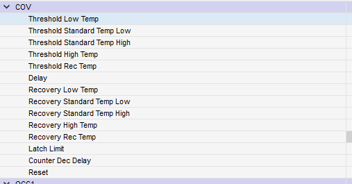
Q2) Additionally, please explain each item related to Cov. (The content and words are a bit confusing.)

Q3) I would appreciate it if you could provide an example as well.

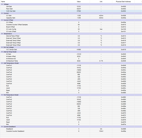
Q4) Please provide support regarding calibration method.

Q5) Please also check how to set up Gas Gausing.
Please check. Thank you.

  • Hey Grady,

    1 & 5.) There is not an specific example. However, I will share the document that goes over completing the learning cycle that discuses setting up some initial parameters on the gauge. https://www.tij.co.jp/jp/lit/an/slua903/slua903.pdf

    2.) The Threshold parameters are the voltage point where COV protection alert will trigger. So if cell voltage is greater than COV threshold then the COV safety alert flag will set. Low temp, Standard Temp low, Standard Temp High, High Temp, Rec Temp are all configurable temperature ranges in the "Temperature Ranges" section in Advance Charge Algorithm part of Data Memory. So the threshold and recovery values are configurable for each temperature range. The Delay parameter determines when a safety alert turns in a safety status and the CHG FET turns off. If the voltage been greater than the threshold value for longer than the Delay time then the protection trips. Recovery parameters determines the voltage when the battery is less than when the protection "un-triggers" and the CHG FET turn back on and the safety status bit clears. Latch Limit determines when the permanent fail event will trigger on the gauge. Counter Dec Delay determines the time period when the COVL Counter is decremented when the battery is in normal condition.

    3.) An example I can provide is lets say under standard temp low conditions, you have the threshold set to 4400 mV, recovery set to 4200 mV, and Delay set to 20 seconds. When the cell voltage of a single cell goes above 4400mV then the SafetyAlert()[COV] will be set to 1. This happens for 30 seconds. Then SafetyAlert()[COV] will clear and SafetyStatus()[COV] will set to 1 and the CHG FET will turn off. Then after some time the cell voltage will drop below 4200mV. Then SafetyStatus()[COV] will clear and the CHG FET will turn back on.

    4.) To learn more about calibration please read section 3.3 of this document: https://www.ti.com/lit/ug/sluubz5/sluubz5.pdf

    Regards,

    Nick Richards