Hi
We are facing some issues related to TPS552882 and found that the output voltage ripple is large and there is obvious part noise under heavy load.
Could you help identify if there is anything that needs to be improved in our design?
Thanks.
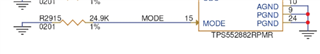
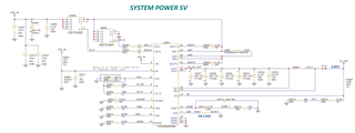
Schematic(Vin:5V to 9V, Vout:5V)
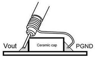
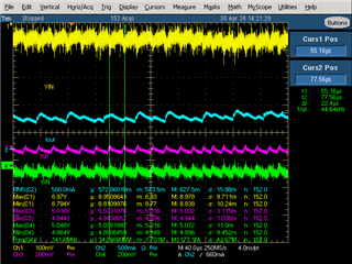
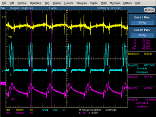
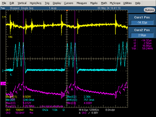
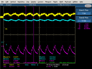
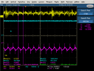
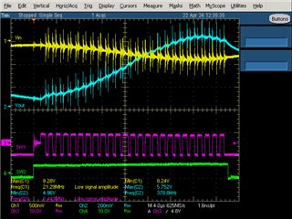
We use the power supply to provide a voltage of 9V and get the following waveform. The voltage ripple is large under heavy load.
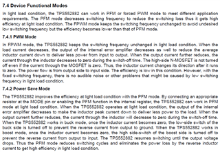
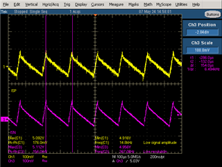
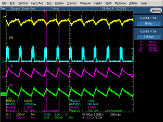
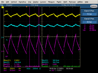
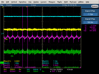
Waveform(lightload)

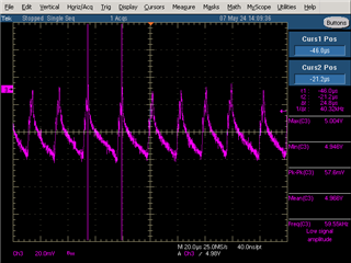
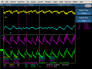
Waveform(heavyload)

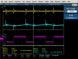
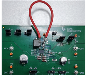
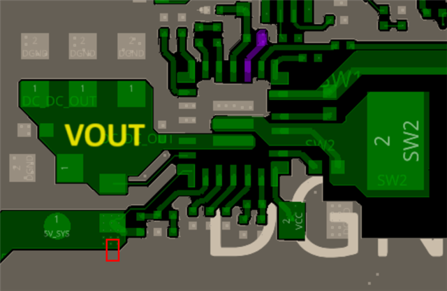
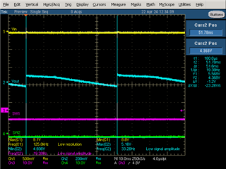
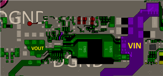
Layout
Best,
Boris.