This thread has been locked.

If you have a related question, please click the "Ask a related question" button in the top right corner. The newly created question will be automatically linked to this question.

UCC3809-1: High number of failing parts

Part Number: UCC3809-1

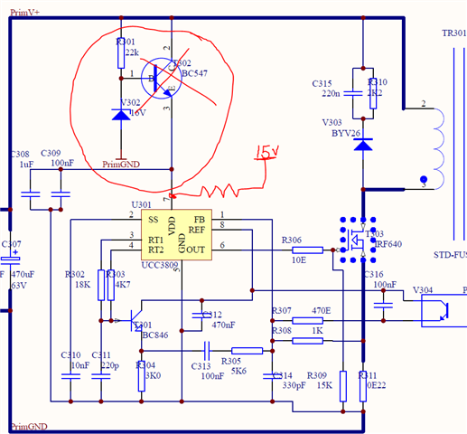
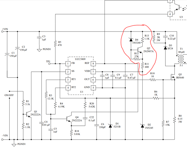
Here at our company we have a product that includes a UCC3809DTR-1 SOIC-8 chip in a flyback topology (schematic included). This product is running in the field for quite some time (10+ years) but suddenly we're experiencing a high number of failures from newly manufactured boards. Our EMS partner builds and tests the product and tells us they have a 100% pass rate, however, we experience 75% failure even without load. I've analysed the failures and narrowed it down to this UCC3809 chip. It fails in either of two ways: 

  1. Most commenly it get's hot (60-100 degrees centigrade). Also I measure tens of ohm between the power pins wiht a multimeter after the part died. When it fails like this the transistor used as a crude voltage regulator naturally gets hot aswell.
  2. Second failure type: the output stays high, driving the switching FET continously which I believe sometimes destroys down-stream components.

In either case, swapping out the UCC3809 for a fresh one solves the problem.

The power supply (24VAC) looks clean on a scope, no spikes, noise to speak of or other transients. The boards even fail without external load.

We didn't experience this in the past but suddenly this is an issue. Could you help me figure out what is going on?

Best regards,

Richard Bekking

TAI_SCHEMATICS (1).pdf

  • Richard,

    the first thing to easily check are UCC3809 top case part markings. Is there any difference in the markings you see between failed vs non-failing controllers? Are all failing controllers having the same markings? Are all non-failing controllers having the same markings?

    If the failure repeatable? If yes, can you describe the conditions? You only mentioned that it fails even  at no load but more specifically does it fail at a certain input/output condition, does it run steady state and then fail when a load is changed or introduced, do it fail at startup, shutdown or some other repeatable line/load/transient condition?

    1. "Most commonly it get's hot (60-100 degrees centigrade). Also I measure tens of ohm between the power pins with a multimeter after the part died. When it fails like this the transistor used as a crude voltage regulator naturally gets hot as well."
      1. What is the measured case temperature when the controller is operating as expected? "Tens of Ohms" measured between the power pins - what pins exactly?
    2. "Second failure type: the output stays high, driving the switching FET continuously which I believe sometimes destroys down-stream components."
      1. What is the "output stays high" amplitude compared to VDD when you are making your measurement? Is the oscillator still operating as expected when this is happening? What is the DC resistance measured between pins 6-7 and 6-5 for a good controller vs a failed controller? 

    If you suspect the output stage failed, have you removed the MOSFET and confirmed measurements of the MOSFET and controller output with the MOSFET out of the circuit?

    Steve

  • Hi Steven, Thank you for your reply! The failure is repeatable. They fail regardless of the load or loadchange it seems. Failure incurs at startup. We have observed the following:

    - First time power on the board, all power rails come up as expected

    - Power down, wait a few minuites, power on: The board either works or fails on the UCC3809.

    Power pins: pins 7 (VDD) and 5 (GND). These two pins measure tens of ohms after failure.

    About point 2: It's has no amplitude because it is a steady DC voltage.

    I'll check the following things today:

    - Comparison of part-markings

    - Measurements between 6-7 and 6-5 for both a good- and a failing controller

    - Repeat the measurements without the MOSFET in the circuit

  • Richard,

    "About point 2: It's has no amplitude because it is a steady DC voltage."

    • DC voltage has an amplitude. I am asking what is the amplitude of the DC voltage you measure on OUT (pin 6-5) compared to the DC voltage you measure on VDD (pin 7-5) for a failed vs non-failed device?

    From your description, it sounds like a failed device is showing a shorted VDD to GND? Does this mean when you try and power on that devices, you get no VREF, no oscillator?

    One area of your circuit I recommend you investigate is the start-up circuit. The UCC3809 ABS MAX IDD current is 25mA but only 100μA is required for startup. Your startup circuit has no current limiting and R301 is serving a dual role of providing T302 base current, Ib, and limiting V302 zener current, Iz. Assuming ~34V at "Prim V+", R301 is seeing ~820μA and this current is then split between Ib and Iz. The collector current of T302 is Ic=hfe*Ib. The BC547 hfe can be anything from 110<hfe<800 depending on the A/B/C version of BC547. hfe is also sensitive to temperature and bias. For the BC547 gain curves below, I marked the red line at the UCC3809 ABS MAX, IDD limit of 25mA. I would say that you really want to assure that Ib<50μA, under all startup conditions, to maintain that IDD~10mA.

    With this in mind, how do you control the collector current in your design? R301 is seeing ~820μA but how do you limit this so that ib~50μA. I don't see a way to do this and if anything about that BJT has changed (A/B/C version, supplier, manufacturer, batch/lot, etc) to where the hfe is somehow higher than what you previously experienced, you may be seeing a situation where IDD>25mA, causing VDD failure on the UCC3809? Your startup circuit is pass regulator that regulates the voltage seen at VDD but there is no current limiting. A quick test I would recommend is to remove T302 and try biasing the UCC3809 through a startup resistor using a DC lab supply. Basically you are setting up a way to control/limit the amount of IDD current into the VDD pin (could also do this by setting the current limit of your DC lab supply to 10mA). Try 15V and R~499k which will limit IDD~10mA. Repeat the condition that previously caused the failure - any difference? If no failure then we need to bias the BC547 differently to limit the IDD current.

    Here's a startup bias example from the UCC3809 data sheet application circuit where R13+R11 are limiting IDD but your circuit does not have this:

    And one more thing just to be aware of is that there is an internal 17.5V, VDD zener clamp inside the UCC3809. Since it appears your startup circuit may not be providing reliable IDD current limit, it is likely this internal zener has failed short and this is why you are measuring such low VDD-GND resistance on a failed UCC3809. 

    Also, if it turns out you do need to redesign the startup circuit, why VDD=15V? The IRF640 is not benefitting from VGS=15V. If you are using the UCC3809-1 (10V/8V UVLO), why not save some gate charge, switching loss and bias the UCC3809 with VDD=11-12V?

    Regards,

    Steve