Other Parts Discussed in Thread: TPSF12C1
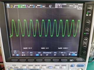
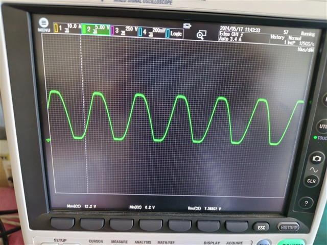
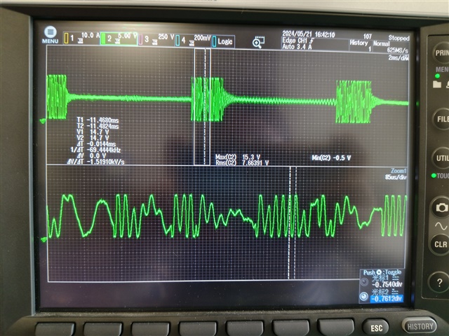
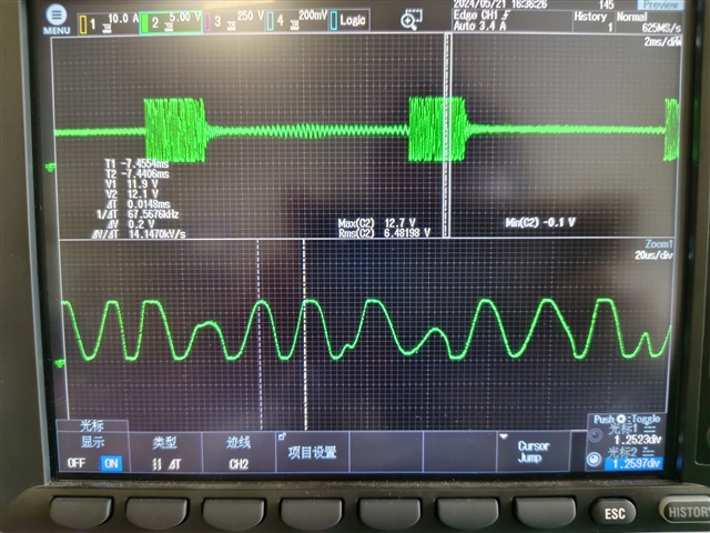
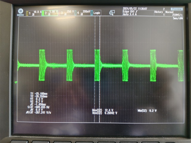
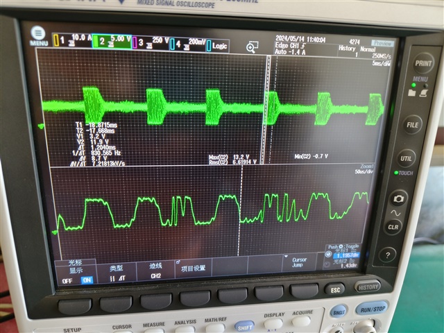
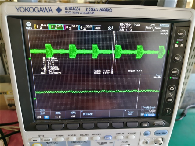
hello,there have very good effect in low-voltage test, but no effect on high test,VINJ have many peak voltage,it is more than 12V
hello,there have very good effect in low-voltage test, but no effect on high test,VINJ have many peak voltage,it is more than 12V


 i
i