This thread has been locked.

If you have a related question, please click the "Ask a related question" button in the top right corner. The newly created question will be automatically linked to this question.

TPS65987D: Spurious behaviour following receipit of RDO message requesting change from 15V PDO to 5V PDO - suspected reverse blocking issue?

Part Number: TPS65987D
Other Parts Discussed in Thread: TPS61022

Hello,

I have encountered an issue with our TPS65987D application in which a spurious reset is observed following receipit of RDO message requesting change from a 15V PDO to 5V PDO.

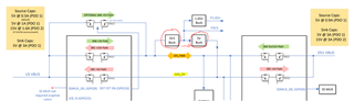
Configuration as follows:

  1. TPS65987D operating as DRP acting as SRCto provide power to an Apple iPad. Upon USB-C connection, the iPad selects 15V PDO (SRC via PPHV1) and charges as expected.
  2. Once the iPad reaches 100% state-of-charge, in some instances, the iPad is observed to send an RDO message requesting switch to the 5V PDO (5V, 0.5A in our applicaion, SRC via PPHV2).
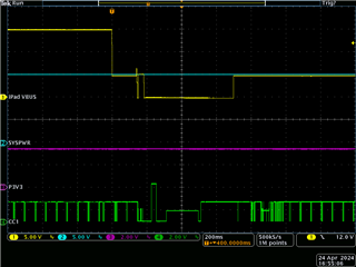
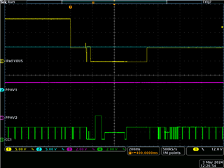
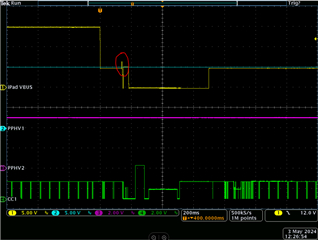
  3. At this point, it appears that an over-voltage condiciton is detected on VBUS, and the link is reset. Please see attached oscilloscope trace.

This issue appears to be very similar to the issues described in the threads below:

https://e2e.ti.com/support/power-management-group/power-management/f/power-management-forum/1292764/tps65987d-data-role-changing-during-power-role-swap#pifragment-323297=2

https://e2e.ti.com/support/power-management-group/power-management/f/power-management-forum/1340955/tps65987ddk-unable-to-swap-power-role-to-source-when-connecting-battery

Attached:

  1. Oscilloscope trace showing VBUS and CC1 traces at point of RDO and subsequent reset.
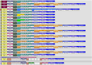
  2. Screenshot of LeCroy capture showing RDO message and subsequent reset.
  3. .pjt file. Please note that this file has had a change made to a non-user confirgrable field made by Conner Gillette, resulting the first thread linked above. Further, please note that the Transmit Source Capabilities, register 0x32, defined in the .pjtt file are overwritten by our own policy manager software at run-time.

I would be gratefu if you could provide any guidance on the above.

Many thanks in advance,

David  TPS65987D iPad config.pjt

  • Hi,

    Thanks for reaching out on E2E!

    An expert will reach out soon.

    Thank you,

    Kevin

  • Hi David, 

    Couple quick follow-up questions regarding your query:

    1. Are there any limitations with using PPHV1 to source both 5V, 15V and potentially other voltage levels in between? 

    2. Can you capture analog waveforms of PPHV1 and PPHV2 alongside VBUS when transitioning from 15V back down to 5V? 

    3. Can you also provide schematic/block diagram and PJT file of your current configuration? I can try to replicate the issue on my end. 

    Thanks and Regards,

    Raymond Lin

  • Hi Raymond,

    Many thanks for your prompt response to my query. I attach a block diagram of our architecture 'PD block diagram, v3, DCA20240430.pdf' - our design is essentially a USB hub with 3 ports supporting PD (1x UFP and 2x DFP). The issue described affects the UFP only (left-hand side of attached diagram).

    To answer your queries:

    1. For the UFP, PPHV1 is used to SRC +15V or SNK +5V, as per the attached block diagram. No intermediate voltages are supported. PPHV2 is exclusivley used to SRC +5V. This is nescessary in our design - we use PPHV1 to 'pass-through' 15V from DFP to UFP, whereas PPHV2 is used to SRC +5V from a locally regulated +5V supply.

    2. In the scope trace originally provided, the cyan trace labelled 'SYSPWR' is the analog waveform on PPHV1. I do not have a capture of PPHV2, however this is connected to a locally regulated 5V supply which dervied via a boost converter from the P3V3 trace (purple). Please let me know if a capture of the PPHV2 net is still required (I'll need to instrument the board and re-produce).

    3. Block diagram is attached 'PD block diagram, v3, DCA20240430.pdf'. The pjt file is attached with the original post 'TPS65987D iPad config.pjt'. In normal operation the source capabilities are 5V @ 1A (PDO 1, via PPHV2) or 15V @ 1.6A (PDO 2, via PPHV1) and the sink capability is 5V @ 3A (PDO 1 via PPHV1). Please note that these PDOs are not defined within the .pjt file, as these are overloaded by our policy management software (i.e. the capabilities advertised on the UFP are a functon of the available power on the DFP(s)).

    Please let me know if I can provide any further details.

    With kind regards,

    DavidPD block diagram, v3, DCA20240430.pdf

  • Hi David, 

    Apologies for the delayed response, can you specify which PJT (or re-attached it in this e2e thread) file you're referring to? I couldn't find the specify pjt you mentioned (TPS65987D iPad Config) in the previous e2e thread and it seems like there were several configs that were tested. I would like to make sure any reviews additional changes (if needed) are done on the same pjt used for this testing. 

    Are you able measure the voltage on PPHV2 and see if at any point there are abnormal behaviors during the transition from 15V to 5V source? i.e. perhaps a voltage spike from the 15V on PPHV1 could've made its way to PPHV2 if the power path didn't close in time.  Another follow up question, during this testing is there anything attached to the second TPS65987D (the one with 5V and 15V sink PDOs)? What is the voltage sitting on DS1 VBUS?

    I also noticed the SYS_5V connected to PPHV2 is feed from a 5V buck, however the 5V buck is also connected to a 3.3V buck form SYS_PWR. Can you explain if this is correctly setup? I'm not sure what the design intentions are but generally speaking a 3.3V buck can't feed into a 5V buck unless it's also able to boost. 

    Thanks and Regards,

    Raymond Lin

  • Raymond,

    Many thanks for your continued support.

    I have re-attached the affected .pjt file, 'TPS65987D iPad config.pjt'. Please note that, as I previously mentiuoned, the Transmit Source Capabilities (register 0x32) defined in the .pjtt file is overwritten by our own policy manager software at run-time.

    I have performed the expeirment again and captured the voltage on PPHV2 (locally derived 5V rail). Please see attached waveform 'tek00000.png' - no excusrion on this net is seen.

    Regarding the two DS USB-C receptacles - one is not connected, the other is connected to a USB-C wall charger which is providing 15V to the system. This voltage is 'passed-through' from PPHV1 on DS1 to PPHV1 on US (in our architecture, both DS ports provide PD sink capabilities and either can be used to derive SYSPWR; the policy manager software sets the SRC PDO on the US based on the power available on the DS).

    Apolgies for the confusion re. the 5V boost - this is a boost converter and is incorrectly labeled 'buck' on the diagarm. This is also a TI part (TPS61022).

    Many thanks,

    David8176.TPS65987D iPad config.pjt

  • Hi David, 

    I will try to replicate this issue using the provided PJT on an EVM early next week. 

    Would you also happen to have the capability to collect PD logs using a PD analyzer/sniffer? These tools are handy with decoding the CC logic to determine the PD messaging between two PD capable devices. 

    Thanks and Regards,

    Raymond Lin

  • Hi Raymond,

    We have a LeCroy Mercury T2P that can be used for PD traffic analysis. There's a screenshot of the output in the initial post - please see zip archive attached to this post (it's a relitively long capture as it was necessary for the iPad to reach 100% state-of-charge prior to chaning from 15V -> 5V)LeCroy capture.zip.

    Regards,

    David

  • Hi David,

    Thanks for getting the PD logs, they are typically very useful.

    Raymond is currently OoO and will be returning next week, and we apologize for any delays in communication during this time.

    Thanks and Regards,

    Chris

  • Hi Raymond,

    Do you have any updates on this ticket or feedback on the files that I have provided? Is the system behaviour as you would expect? It would be useful to get your feedback as soon as possible as we are schedulded to conduct USB-IF testing in early June and I expect this may cause issues if unresolved.

    Thanks,

    David

  • Hi Raymond - I have not received any support regarding this issue. Are you able to offer any comment on the issue I've captured?

  • Hi David, 

    Apologies for the delay in response. 

    Does this potential RCP only happens with this specific iPad device? Are you able to test a 15V to 5V source transition using other PD capable sink devices to see if it's easily replicable? 

    Also I noticed in the Lecroy PD logs a couple parts I want to clarify with you:

    1. FR Swap occurred at packed 2065-2067, is this scenario intended and feature supported on your device? 

    2. At Packet 2082 the iPad is advertising source cap and Jerboa is the sink, is your system booting up from a dead battery scenario and if so how is the dead battery flag being cleared?

    3. After the PR Swap at packet 2090, is SYS_PWr always at 15V? Is there ever a time where SYS_PWR is not present? 

    Thanks and Regards,

    Raymond Lin

  • Hi David, 

    After another look another suspicion is possibly OVP on VBUS, see the circle point in the screenshot below:

    Also referring to this PJT to check, upon further inspection the configuration doesn't seem to align with the block diagram you previously provided (only 1 source PDO of 5V/0.5A, no power path configured to be DRP). Does your system have an EC that's re-configuring the PD's register on the fly depending on the circumstances? If so, what is the PD config when a 15V/3A source is connected through the other sink port? 

  • Hi Raymond,

    Many thanks for your comments. My responses:

    I agree with your comment re. the OVP on VBUS highlighted in the scope trace - I believe this event is causing the link to reset. This is why I titled this thread 'suspected reverse blocking issue?' When transitioning from 15V -> 5V, PPHV1 will be at 15V (see trace) and PPHV2 will be at 5V - the only way for this OVP on VBUS would be for PPHV1 failing to reverse block? We previously encountered an issue with the reverse blocking of the power path that Conner Gillette resolved for us (this required a change to a non-user configurable parameter) - please see linked thread in OP.

    Please ignore the sorce PDO in the .pjt file - these are overwritten by en embedded controller dependent upon the power available (the source capability advertised on the UFP - to charge the iPad - is dependent upon the available power on the DFP(s)). If at 15V/3A source is connected on either of the DFPs, a source capability of 15V/1.6A will be advertised to the iPad.

    1. FR swap is supported in this application (iPad transitions from SINK to SOURCE if external power to the hub is lost). In the test described external power is available coninuously, the iPad is charging but the issue occurs when the iPad requests contract change from 15V -> 5V. So I don't believe this is linked to FRSwap?

    2. Dead battery flag is cleared by embedded controller. The product does not include any internal battery. It can be inititally powered from any of the external USB-C ports.

    3. SYS_PWR should always be present in this test (it certainly is on the scope trace - see PPHV1, which is connected to SYS_PWR.

    Grateful if you have any more comments on the above. We are conducting USB-IF testing next week so I may have additional information/further queries to bring to you.

    Kind regards,

    David