Other Parts Discussed in Thread: LP87644Q1EVM
Dear,
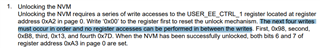
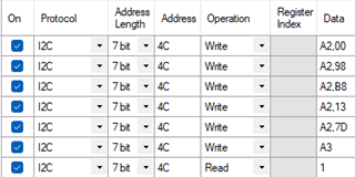
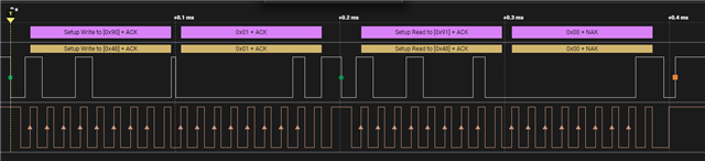
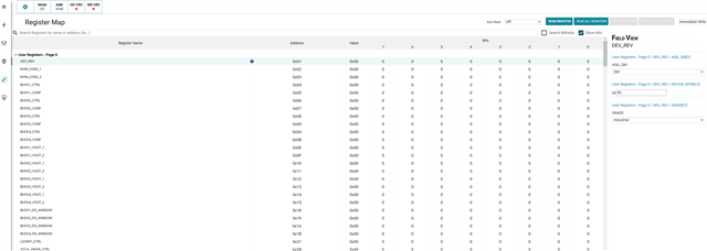
We have a LP876411B4RQKRQ1 on a custom PCB. To operate it properly, we would like to change the NVM through I2C as asked before (link). Normally, this should work with any I2C host as mentioned in the answer. When trying this on the evaluation module (LP87644Q1EVM) with a generic I2C host and access to VCCA, VIO, SCL, SDA, and GND, this works as expected. However, when running the same I2C commands on our generic PCB we can find the LP876411B4RQKRQ1 at the correct I2C address, but we cannot update the NVM.
I read on the forums that multiple people have the same problem. In (link), the user registers were locked, but this has been taking care of in our I2C command list by writing on register 0xA2 on page 0 as explained in the “Scalable PMIC NVM Update Guide” (link).
I also saw two topics related to my question on the forum (link & link) without any solved responses.
Could you help me with this problem, or direct me the correct documentation to solve this one?
Kind regards
Gertjan