This thread has been locked.

If you have a related question, please click the "Ask a related question" button in the top right corner. The newly created question will be automatically linked to this question.

LP8764-Q1: I2C issues with custom PCB

Part Number: LP8764-Q1
Other Parts Discussed in Thread: LP87644Q1EVM

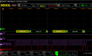
I have a custom PCB that uses an LP876441B1RQKRQ1 and PIC to control it via I2C. The code has been tested with the LP87644Q1EVM and a PIC dev kit and there wasn't an issue enabling and changing the buck's voltage. On the PCB however there's been issues communicating in a general sense. The I2C lines are working, but it's just receiving 0x00 from LP8764, and enabling and controlling the chip doesn't seem to work.

I've verified that the i2c address is 0x4C by trying 0x48 (EVM address) and getting NACK errors, so it confirms that I2C is "working" with at least acknowledging the address. The most baffling part is that I was able to get it to work once, where each buck was enabled and outputting the correct voltage, but multiple power cycles and retries from the PIC have resulted in the same issue of nothing really happening. There was also a short period where the I2C was returning actual values, but again, a power cycle seemed to put it back in its current state.

I'm not sure if there's something I'm missing, or if there's a startup condition that's causing this issue. I've attempted to delay configuration by 5+ seconds after power is applied but that had no change. Verified that VDD_LDO has about 1.8V output. The actual circuit is the same as the LP87644Q1EVM, with a slight difference being the feedback is setup, although it's not configured in the chip.

Any direction would be greatly appreciated.

  • Hi Nicholas,

    Thanks for reaching out. The expert engineer of this device was out of office. Please expect response by end of today. 

    Br,

    Ishtiaque 

  • Hi Nicholas,

    The device LP876441B1RQKRQ1 NVM (the internal pre-configuration) is totally different from LP87644Q1EVM chip configuration. Have you flashed current custom PCB device with new NVM configuration. Because device is capable to maintain NVM config (or re-flashed to non-volatile memory) and there is no need for extra PIC device to update registers. 

    In current scenario are you having VCCA power before talking to device over I2C and VIO voltage in place as well?

    Br, Jari

  • The LP87644 is planned to be turned on and off as needed, so the PIC is necessary to enable and disable. I did try to read back the NVM registers (using address 0x4D instead of 0x4C) but I still get 0's as a reply when I read back the registers.

    As for the VCCA, It's powered via USB 5V, and VIO is powered by a 3.3V regulator that also powers the PIC and I2C pull-ups. I've set it up so it waits 5+ seconds a few times, so the power should be applied before that, but that has no change.

    Edit: Some additional information. I was able to capture the I2C bus and we're able to get some acknowledgement back, but again, the line just goes to 0 when we request the information. Currently it should just return the buck4 Vout1 voltage, which I'm expecting a default value or the last one I set but it's just returning 0.

  • Hi Nicholas,

    So have you created new NVM for PMIC and reprogrammed it to EEPROM? I'm referring to update guide https://www.ti.com/lit/an/slvaf93a/slvaf93a.pdf.

    What is very misleading here that why it would have worked in the beginning but now out of sudden gone not responsive. 

    So if miscommunication is caused but PMIC it has to be HW reset state, OVP on VCCA or two PFSM errors happened.

    Br, Jari

  • Looked through the update guide, and attempted do the unlock sequence but still received 0's when checking register 0xA3. Also verified with the dev board that the commands are correct.

    If it is some reset state or error, how can I clear or verify it? Is there a pin or command that I would need to issue?

  • Hi Nicholas,

    Are you sure you haven't update I2C1 address? Since if device is functional, meaning not caused permanent damage, it should reply to I2C expect in HW reset states. What is your VCCA voltage level? 

    Br, Jari

  • I did scan and there i2c1 address 0x13 that's responding, but it doesn't seem to do anything as far as I can tell. Not sure what the address is used for.

    Checked the VCCA input voltage and it's 4.92V, this is coming in from a USB 5V in

  • Hi Nicholas,

    The device expert is out of office. Please expect delayed response by Monday 18th. 

    BR,

    Ishtiaque

  • We tried to read from the chip using the GUI interface, but had read errors

    It was followed by an EEPROM locked error:

    We had an earlier PCB revision that had other issues, but the PMIC was populated. When trying the same method we are able to communicate and program that unit without an issue. Unsure how this occurs as I don't attempt any type of locking sequence.

  • Hi Nicholas,

    Could you elaborate what changed between PCB revisions? Any voltages, caps, connections? 

    And now you're using same GUI and files as with previous revision?

    Br, Jari

  • The previous (v1.0) revision had the LP8764 disconnected from any load, and the newest revision (v1.1) does have the LP8764 connected to the load. We  removed the LP8764 from the v1.0 board and used it to replace the LP8764 on the v1.1 board. The v1.1 began working normally after it's replacement.

    This was testing with the same GUI at all times, as they were done side-by-side before removing the LP8764. 

    It's unclear if there was something that caused the chip to lock up like it did, but I don't see a way that we can either reset the chip or get it out of this state. Any suggestions for preventing this in the future is necessary as we are still in the prototyping stage and need a PMIC to work correctly.

  • Hi Nicholas,

    I see. So in principal you might have locked the device during NVM flashing and this is irreversible. So while flashing you must avoid selecting to lock device. 

    One other thing is that if flashing is interrupted it can cause some weird issues but it is very rare. The thing that device is not responding at all is also very strange and shouldn't happen when used correctly. 

    Please let me know if you need further assistance. 

    Br, Jari

  • It is very strange which is the issue. Changes were only made to page 0 initially, so it shouldn't have interacted with NVM at all. The only time we started to interact with the NVM was after it locked up, and even then it was mainly to read the data back.

    We have a few prototype boards and they all seemed to run into this issue, so if there's something that is causing the LP8764 to lock up either due to a design flaw or process malfunction we need to know so we can prevent it from happening. It's also once thing for the chip to get locked up, but communication was dead so we couldn't even confirm it's the case.

    Is there anything you're aware of that can cause the communication to cease, even if the i2c address is acknowledged? A short, or and i2c message corruption or anything like that? If we are going to continue using the chip we need to prevent issues like this from occurring when we inevitably make more units.

  • Hi Nicholas,

    You're talking about page 0 changes. Did you flash the NVM content? Since if you want to make LP876441B1RQKRQ1 device to work in your configuration you need to flash NVM. Do you have *.json file to share?

    Br, Jari