This thread has been locked.

If you have a related question, please click the "Ask a related question" button in the top right corner. The newly created question will be automatically linked to this question.

UCD3138ALLCEVM150: Fault Pins Assignment in LLC EVM Firmware

Part Number: UCD3138ALLCEVM150
Other Parts Discussed in Thread: UCD3138, , UCD3138A, UCD3138PFCEVM-026, PMP40586, PMP20978, TIDA-00512

Hi Team,

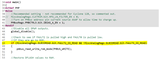
I am going through UCD3138_LLC_HB firmware. I have few doubts and kindly clarify the same. I have found the below code in main.c.

//Check to see if FAULT2 is pulled high and FAULT0 is pulled low.
//If they are go to ROM.
if (MiscAnalogRegs.GLBIOREAD.bit.FAULT2_IO_READ && !MiscAnalogRegs.GLBIOREAD.bit.FAULT3_IO_READ)
{
pmbus_read_write_rom_mode(PMBUS_WRITE);
}

Only fault1 is configured as GPIO after the above condition in init_gpio() other all faults pins as it is.

First of all the comments given in the code and actual condition in the code not matching ( Comment say fault2 & fault0 but actual condition is fault2&fault3). 

In UCD3138ALLCEVM150, as shown below fault2 (EXT_OVP_DISABLE) is using as output from UCD3138A for driving the FET Q5. The default pin configuration for fault2 as input and fault since we didn't configure this pin before that above condition.

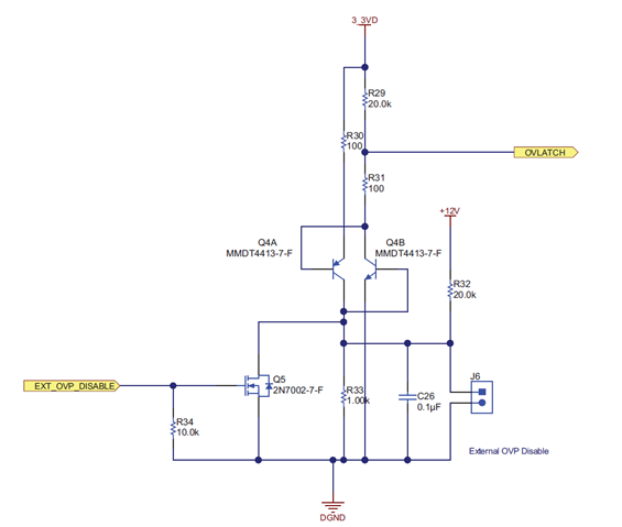
1. The firmware didn't configure fault2 pin direction as output and GPIO pin then how it will be used for driving Q5?

2. How the same fault2 pin state used for checking whether to clear checksum or not? Instead, we can use fault3 (OVLATCH) which can be controlled.

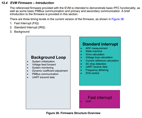
3. ON/OFF given as fault3 that means if the ON/OFF (FAULT3) is high means UCD3138 detects as fault so we need to set this pin always low? If the fault pin set to high means it will generate fast interrupt and disable the PWM?

4. Is there any document which explains the firmware flow of LLC or any other application for UCD3138A as it is not regular c2000 code flow? (Other than training labs and TRM)

Thanks in advance.

  • Hello Yedida,

    The code is used as a backdoor hardware reset for the UCD3138A to go into ROM mode. Please see the following E2E posts that explain the code in more detail: 

    I do not believe we have a good in-depth walkthrough of the LLC-HB firmware. We do have good documentation of the PFC EVM firmware. The PFC firmware is much more complicated than the LLC-HB firmware. So, if you can understand the PFC firmware, then understanding the LLC-HB firmware will be straight-forward as long as you know the LLC design fundamentals. The EVM User's Guide has a good firmware overview in section 12.4 on page 37 (EVM Firmware - Introduction). Many of the architecture ideas can be transferred to the LLC.

    PFC Firmware Documentation:

    It may also be helpful to look at other Half Bridge LLC reference designs. We have 3. The LLC-HB EVM used to be a reference design before becoming an EVM so there is also a reference design test report available.

    Regards,

    Jonathan Wong

  • Thanks for the quick reply. Kindly let me know what is the intension of using FAULT2 pin for driving Q5 in LLC EVM ? Without configuring as gpio with direction as output?

  • Hello Yedida,

    I will get back to you about this tomorrow.

    Regards,

    Jonathan Wong

  • Hello Yedida,

    Reposting code below:

    //Check to see if FAULT2 is pulled high and FAULT0 is pulled low.
    //If they are go to ROM.
    if (MiscAnalogRegs.GLBIOREAD.bit.FAULT2_IO_READ && !MiscAnalogRegs.GLBIOREAD.bit.FAULT3_IO_READ)
    {
    pmbus_read_write_rom_mode(PMBUS_WRITE);
    }

    Yes, the comment is a typo. The comment should say FAULT3 instead of FAULT0. This code was taken from the Open Loop EVM board and the FAULT0 pin is used for the hardware backdoor. 

    Regarding the intention of the FAULT2 pin, including the FAULT2 is meant to be a robust hardware backdoor. If your UCD3138 is locked into flash mode, then you want some sort of hardware backdoor that will switch the UCD3138 back into ROM mode. This will be purposely driving a pin high or low. This hardware backdoor must also be the FIRST thing that is run in the main loop. Thus, as long as you restart the power (power cycle) to the UCD3138, then you know that the hardware backdoor code will run. Notice how the code is one of the first commands in the main loop. 

    However, we do not want this backdoor to be set off accidentally. Thus, a robust hardware backdoor must be only triggered in such a way that the user must have intentionally pulled signals high or low. Having two separate pins be required to do this is one way, which is why both the FAULT2 and FAULT3 pins are considered for a backdoor. 

    Because this code is the one of the first commands, it will not affect the rest of the code. After the code reads the value of the FAULT2 pin, the firmware will go into the main loop, where the FAULT2 pin may or may not be driving a FET. So, this code doesn't affect the Q5 function. 

    FAULT2 was chosen as the second pin in the hardware backdoor because, by the nature of the schematic, you will need to intentionally drive it low. If your UCD is locked up, then you can take a 3.3V external supply, solder a jumper wire and supply voltage to FAULT2 while shorting FAULT3 to ground. This combination of actions is very unlikely to occur just on accident. So, it serves as a robust backdoor. If you have no other option, then this is what you can do to unlock your UCD3138.

    Regards,

    Jonathan Wong

  • Hi Jonathan,

    Thank you so much for the detailed explanation and now I understood clearly. But still I have one doubt, without configuring fault2 pin as output gpio how it can drive the Q5? (Because code configuring only fault1 as output gpio after the back door condition ). Is it intentionally left for user to configure fault2 pin as output gpio if I want it to drive Q5?

  • Hello Yedida,

    I do not see any code that configures the FAULT2 pin as an output in the LLC-HB firmware. You are right, it might be intentionally left to the user to configure if you so choose to drive Q5. The original author of the firmware is no longer available so I assume they included the hardware connection but never implemented the feature in the firmware.

    Regards,

    Jonathan Wong

  • Thanks for the quick reply Jonathan. I had one final doubt, why the checksum verification implemented in ucd devices which may cause locking up device to not come back to rom (If there is any firmware bug) which I didn't see in c2000 Devices?

  • Hello Yedida,

    C2000 uses a propriety computer architecture so their firmware is not compatible with UCD. The UCD3138x devices are Arm-based (Arm7) computer architecture and does have the possibility of being locked in flash, which is why a hardware backdoor is recommended for debugging. The C2000 MCUs might also have a similar problem but that would be a question for the C2000 team on how they overcome locking up in flash. If you are interested, please submit a new E2E question and tag the C2000 products so we can direct you to the right experts.

    Regards,

    Jonathan Wong 

  • Sure I will do. Thanks Jonathan