This thread has been locked.

If you have a related question, please click the "Ask a related question" button in the top right corner. The newly created question will be automatically linked to this question.

LM5170-Q1: LM5170-Q1 MOSFET failure detection

Part Number: LM5170-Q1
Other Parts Discussed in Thread: LM5170

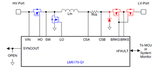
We want to use the MOSFET failure protection feature in this LM5170-Q1 by leaving the SYNCOUT open. However, nFault was remained shutdown (Low state) even there is no short circuit between high-sed and low-side of MOSFETs. My buck converter 48V to 12V is working fine if the MOSFET failure protection is disabled (SYNCOUT pin connected to a 10K to GRND). Please let me know what I'm missing here. Thank you.

  • Hi Chung,

    May I know if you used the circuit breaker (a pair of back-to-back MOSFETs) as shown below?

    The failure detection function must be deactivated if the circuit breaker is not present, or if the circuit breaker FETs are not controlled by the LM5170-Q1.

    Best Regards,

    Feng

  • Hi Feng Ji,

    Thank you for your reply. My original design does not have the circuit breaker (a pair of back-to-back MOSFETs) at the 12V output. To protect the over voltage to the load when MOSFET failed, I need to add the circuit breaker and enable the MOSFET failure protection this time by leaving the SYNCOUT pin open as shown in your diagram. However, due to this failure detection function enabled, the LM5170-Q1 is remained in shutdown mode even MOSFETs are not shorted! nFAULT pin is never pulled up HI, when EN1 & EN2 are HI, UVLO > 2.5V, and VCC> 8V! Please note that the LM5170-Q1 is working fine when failure detection mode is disabled (SYNCOUT pin with a 10KR connectred to GND).

    According to one of your TI Guru, Youhao, it looks like the mechanism to detect MOSFET failure is to sink or source 20mA to CSBx pin and detect the failure by monitoring SWx voltage pin. If this is correct, I'm afreaid that this SWx pin may not be able to raise to 4V-6V or lower to 1V to determine the MOSFET short due to a large output capacitance connected to CSBx in my circuit as shown in the attached diagram. In this mode, the nFAULT is only pulled up HI when 1.5V < UVLO < 2.5V! Please let me know how to make this MOSFET failure detection work. Am I missing something?

    Another question is about OVPB pin to set the max output voltage at the low side. I noticed that the soft start will run until it reach this voltage before transferring to the control loop. Will this OVPB voltage setpoint is also the over voltage shutdown fault? Let say I'd like to have the LM5170-Q1 shutdown the gate drives when the votlage is reached 16V but I prefer the soft start running until it reaches my regulated voltage which is 12V to prevent over voltage at start up to the load. How can I do that? How to separate the max voltage in soft start during the start up and the over voltage protection?

  • Hi Chung,

    You should connect the output capacitor to LV-Port but not CSB.

    Soft start has nothing to do with OVPB. I suppose you do not have a soft start circuit.

    Please refer to LM5170EVM user's guide. The circuit below is designed for soft start.

    Best Regards,

    Feng

  • I have to think about moving the output cap to the output of the breaker circuit so that the failure detection in LM5270-Q1 can be used. 

    In term of the soft start circuit, we do implement it similar to the one in the LM510EVM. However, it seems that the soft start only stops when the low side ouput reached voltage set at OVPB! After that the ISETA will take the control to regulate the output voltage. Can you explain what is the OVPB setting for if it's nothing related to soft start?

    Your help is really appreciated.

  • Hi Truong,

    Please try to increase C90 to extend the soft start time. And please minimize the cap at SS-pin.

    Best Regards,

    Feng

  • Can you explain why I should increase the soft start time? I prefer the soft start is just long enough to bring the output voltage close to the regulated voltage setpoint of 13.5V, but not ~19V, which is the Vovpb set point. Please review the attached graph that shown the soft start in my circuit. Clearly, the soft start was running until it hit the max output voltage of ~19V, where the voltage setpoint at OVPB pin (Vovpb=1.185V x (68.1K+1M)/68.1K=18.59Vdc). Does the LM5170-Q1 shutdown (nFault -> LOW) if the low side output is reached Vovpb set point? Any hysteresis after shutting down due to output reached Vovpb? To reduce the overshoot in soft start,  I did try to reduce the Vovpb to ~15.5V but it may cause the output shutdown prematurely during normal operation. Any suggestion to prevent soft start from overshoot at the low side output? Thank you.

  • Hi Truong,

    The output voltage stops increasing until it hits OVP threshold (19V). The overshoot is cause by the loop response. Soft start is used to eliminate the overshoot. I believe soft start is not taking effect now.

    In Buck mode, when the OVPB pin voltage is above the 1.185-V threshold, the SS capacitor is discharged and held low until the overvoltage condition is removed.

    Can you share a waveform with the inductor current, the output voltage, SS-pin and the voltage of C90?

    Best Regards,

    Feng

  • Hi Feng,

    When I lowered the Vovpb to ~15V the output no longer has overshoot but stays at the regulation voltage. Can you confirm this LM5170 IC is reliable? I heard rumor that this LM5170 IC is somehow damaged (internal shorted) and no one knows the root cause. We did experience some damaged to this IC and we could not determine the root cause. Please let us know whether we should continue to use this IC in the design or select a different one more reliable.

    Thank you very much for your help.

    Chung T

  • Hi Truong,

    I didn't see any reliability issues with LM5170.

    Best Regards,

    Feng