This thread has been locked.

If you have a related question, please click the "Ask a related question" button in the top right corner. The newly created question will be automatically linked to this question.

BQ76952: BQ76952 Host Cell Balancing

Part Number: BQ76952

https://e2e.ti.com/support/power-management-group/power-management/f/power-management-forum/1346048/bq76952-bq76952-host-cell-balancing?ReplyFilter=Answers&ReplySortBy=Answers&ReplySortOrder=Descending

Can we reopen the above thread? Issue is not yet resolved. 

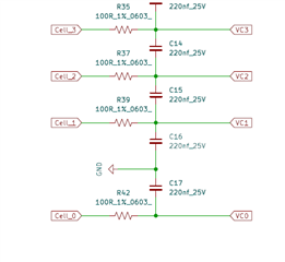
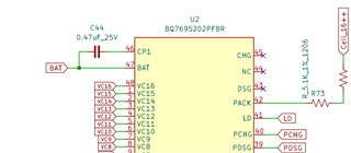
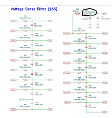
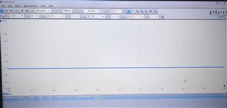
We tried to capture data on scope to see if cell balance was happening, ut we see a flat line and not balancing taking place. Also we tried to remove Q11 to make it host balancing with internal FETs but still no success. 

But at the same time reading from CB_ACTIVE_CELL() show same value as write to enable cell balance. 

  • Another experiment tried, we removed R39, R42, C15, C16 and C17 to see if AFE was actually enabling the cell balance on Cell 1 . Even after this we could not see any pulse there too. 

    By removing above mentioned components we also checked the output voltage @ VC0,VC1 & VC2 individually for each pin but there is no expected results ( we manually tried to turn on/off balance resistors but output still remain constant with no change to its initial state)

    By any means in Host Controlled Cell Balance is it necessary to also set CB_SET_LVL ? 

  • We need urgent help to resolve this since we are going into production in few weeks time

  • Hello Vikram,

    Did you use the scope directly on the IC pins? It would only be visible if you probe directly on the pins, it cannot be on the cell-side. Do you have the scope shots of these pins?

    No, CB_SET_LVL() would not be needed for host balancing. Do you have a logic analyzer capture of when you send the cell balancing command and also when reading back which cells are being balanced?

    Removing the filter resistors would not be good, because then you would not be able to see any voltage change happening as there's no voltage drop happening.

    You could try enabling balancing for Cell one and put the scope on VC0 with respect to Vss to see what is going on, or VC1 to Vss.

    Best Regards,

    Luis Hernandez Salomon

  • Hi, Ajay here.
    As you have suggested, " You could try enabling balancing for Cell one and put the scope on VC0 with respect to Vss to see what is going on, or VC1 to Vss."

    We have tried this.
    When we turn on cell1 ,graph is look likes across vco to vss.


    AFE IS WORKING , MOSFET IS NOT TURNING ON IS OUR OBSERVATION. WHAT NEXT WE SHOULD DO.

  • Hello Ajay,

    Have you tried using other cells? Such as VC2 to VC0?

    Can you upload the image to E2E? I cannot open it from my side.

    Is there any protection condition going on? If a protection condition were to happen, that could also stop balancing.

    Best Regards,

    Luis Hernandez Salomon


  • This waveform is for vc1 to vss and same for vc0.

    I have already check for protection scenario, no protection is active.

    Software reads afe is working, afe also looks fine, but mosfet is not turning on, please help what may be the reason for not having cell balancing.

  • Hello Ajay,

    A protection does not need to be triggered to stop balancing, if it detects any fault condition present, balancing will stop.

    What is your sequence to cell balance the cells? Can you generate a .gg.csv file for me to check?

    Did you check with a logic analyzer to make sure that you are sending the right sequence?

    For example, for Cell 1 to balance, the following sequence would need to be send:

    • W: 10 3E 83 00 01 00   - Set Cell 1 to be balanced
    • W: 10 60 7B 06             - Send checksum and length so cell balancing takes effect
    • W: 10 3E 83 00             - Write 0x83 to 3E and 0x00 to 3F (Writing 0x0083 to 3E/3F so that we can read from it)
    • R: 10 40 2                     - Read from 0x40 transfer buffer to confirm which cells is being balanced. (Should return 0x0001)

    Best Regards,

    Luis Hernandez Salomon

  • Hi, I have check with above sequence. 
    The approach followed, I used evaluation board, bq studio and bms .
    I have connected bq studio with evaluation board , through evaluation board i want to check my afe cell balancing of bms.
    For same purpose, using I2C connected both hardware.
    But result I got is the same. 
    Before turning on cell balancing, voltage across cell 1 is showing 3.4 volt.
    When I turning on cell balancing using above sequence, I got following results.
    R39=3.4 V,
    R77=3.4 V.

    Need further support. 


    Is there is anything I missed on software/hardware side?


  • BMS here refers to the the custom hardware we built for battery pack. This is going on for very long, if possible we can connect on private email communication at vikram.jain@matel.co.in to share any further details like layout and schematics. Or we can have a online meeting on Zoom or Teams. 

    Also on the other post "https://e2e.ti.com/support/power-management-group/power-management/f/power-management-forum/1346048/bq76952-bq76952-host-cell-balancing?ReplyFilter=Answers&ReplySortBy=Answers&ReplySortOrder=Descending" I have put all the register values that we configure in software. 

  • Also we are noticing that when the BMS is turned off there approx 500mV of drop across R23. Also when the device is on there is 60mV of drop across same resistor. 

    What could be the reason for this?

  • Hello Vikram, Ajay,

    It does not make much sense to me that there is 0.5-V drops across R23 when the device is OFF, specially since it is much lower when ON.

    That would indicate there is 5-mA of current flowing somewhere. 

    When I turning on cell balancing using above sequence, I got following results.
    R39=3.4 V,
    R77=3.4 V.

    What did it show when you read from the subcommand I mentioned in my example? That would indicate when a cell is being balanced. 

    Now, there is something important that I am noticing. The balancing FET may not work for this application, the turn-on voltage of this FET can be as high as 3-V (as specified in its datasheet). There is guaranteed way that this external cell balancing circuit would work properly with this FET. 

    Even assuming our recommended max of 100-Ohms for the input resistors and a 4.2-V battery, the internal balancing current would be 4.2-V(100+25+100) = ~18.6-mA, which would generate a gate-source voltage of ~1.8-V. Well below the max turn-on voltage of this FET.

    For example, in our reference designs we have used the DMG2302UK-7 in the past, which has a maximum turn-on voltage of just 1-V. You would need to find a balancing FET that has a max turn-on voltage below what our circuit could generate.

    Best Regards,

    Luis Hernandez Salomon

  • What did it show when you read from the subcommand I mentioned in my example? That would indicate when a cell is being balanced

    We did read back 0x0001, as you mentioned in your example. Which ever cell we turn ON balancing reading from 0x0083 gives us the same result which tells us that AFE is turning ON the cell balance, but we do not see the external FET turning ON and actual balancing happening. 

  • Hello Vikram,

    I would measure across the drain-source of the FET of the cell being balanced to see if balancing is actually happening (With an oscilloscope).

    If it is ON the voltage would be close to 0-V, when it is OFF the voltage would be roughly the cell voltage.

    Now, keep in mind my comments about the cell balancing MOSFET that was chosen. It may not work for all cases/FETs due to its very high turn-on voltage.

    Best Regards,

    Luis Hernandez Salomon

  • Hello Luis, 

    We tried with MMFTN2316K MOSFET and the results are still the same. We do read what we set from 0x0083 resistor. We had also tried to remove the mosfet and allow balancing with internal MOSFETs, even that was not working. 

    We tested balancing around 4.05V on battery pack. The transmission of data and checksum are all okay. To validate more from software point of view is there anything that could restrict balancing? 

    We really need immediate support now either from Hardware or Software we need to solve this immediately. 

    Regards

    Vikram Jain

  • Hello Vikram,

    Any protection conditions (Besides OVP), and temperature measurement could cause the balancing to get cancelled. 

    Otherwise balancing should be happening, like shown in the Cell Balancing With BQ769x2 Battery Monitors application note.

    I'd check with this app note and double check all your settings to make sure all is okay. Cell balancing should be working and should be visible by measuring with an o-scope directly on the pins.

    Best Regards,

    Luis Hernandez Salomon

  • Hello Luis, 

    There was slight error from my side the main bug was the MOSFET, after changing to MMFTN2316K and on top of this I had to disbale sleep and also prevent sleep when balancing. After doing these changes balancing seems to be working. 

    Thanks a log for your help. Another point is that 

    when the BMS is turned off there approx 500mV of drop across R23. Also when the device is on there is 60mV of drop across same resistor. 

    What could be the reason for this?

    I have provided the schematic reference for this above. 

    Regards

    Vikram Jain

  • If I power up the board for the first time (Using resistor ladder, turning ON 48V first time), the current drawn from R23 is just 24mV. 

    Then if I wake up the device using Ignition and then turn off, (not the 48V supply, just the ignition) the drop across R23 is 400mV. Looks like some resistor settings that could be causing this, can you guide me to look at appropriate register settings in sleep mode to check if they are enabled incorrectly?

  • Hello Vikram,

    Glad to hear the cell balancing has finally been solved! Smiley

    I am a bit confused by "the device is OFF", is the part in SHUTDOWN or in another power mode? Still, 0.5-V across the R23 resistor would indicate that there is 5-mA flowing through it, which is very strange.

    Could you send me your schematic to review it, just to make sure all is okay? You can send this on private messages if you do not want to post it publicly. 

    Best Regards,

    Luis Hernandez Salomon