This thread has been locked.

If you have a related question, please click the "Ask a related question" button in the top right corner. The newly created question will be automatically linked to this question.

BQ24092: Low Charging Current

Part Number: BQ24092

Hi, I've set up a test circuit PCB using the product noted above but can't seem to achieve the programmed charging current of 915mA. 

My set up is as follows:

  1. The battery is an 18650 Li-Ion cell, 915mA charging current, 4.2V cell voltage. 
  2. A DC power supply set to 5V, 1.2A is being used to source the circuit. 
  3. A benchtop multimeter is being used to measure current between the OUT (pin 10) of the BQ24092 and the cell. 

For the circuit

  • ISET is pulled down via a 590Ω resistor to achieve 915mA of charging current. K(Iset) = 540 -> R=540/0.915=590Ω
  • ISET2 is pulled down to ground to disable current limiting for USB source
  • PG and CHG have LEDs and 1.5kΩ resistors pulled high to the OUT pin. Both are illuminated
  • 10µF filter caps are used on IN and OUT of the IC
  • An NTC (TH11-3H103FT) is used. Similar to the one in spec sheet. I've also tried pulling this to ground via a 10k resistor.

Things I've tried:

  • The voltage at ISET is 1V. This should yield ~1A or so of current
  • I've tried shunting the TS pin to ground via 10kΩ resistor. This did not change the behavior. 
  • I've tried removing the Ammeter, but the DC power supply only ever supplies 180mA, indicating that the circuit is only charging at ~170mA of current. 
  • I've built a separate circuit, using a breakout board for the BQ24092 IC. The same behavior was observed - indicating this isn't just a bad IC or bad solder joints. 

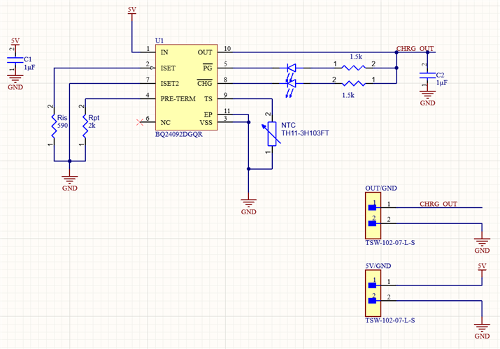
Below is a screenshot of the circuit:

  • Hi,

    Could you please provide the charger operating conditions such as VIN, ISET1 voltage, VOUT, ISET2 voltage, TS pin voltage?

    Thanks,

    Ning

  • Thank you for your reply,

    I measured the following:

    Vin=5.52V
    ISET1=1.4V
    Vout=3.24
    ISET2 = -120mV  (basically 0V)
    TSPIN = 120mV (basically 0V)

    Throughout measuring, the current was 256mA between Vout and the Battery cell anode. 

    I also tried spraying the circuit with a compressed air can to lower the temperature. This had no effect. 

  • I forgot to mention, the battery was discharged to 2.5V prior to connecting it again for this test. 

  • Hi,

    Is there any battery protection circuitry in between BAT pin and the battery pack or does the battery have built-in battery protection? The battery protection may disconnect the battery from the BAT pin of the charger under certain conditions such as UVP.

    Thanks,

    Ning.

  • No its connected directly. I've tried two batteries and had the same ~250mA current limit. 

  • Hi,

    With a battery of 2.5 V and input of 5.52 V with a charge current of 915 mA, the user is requesting 2.76 W to be dissipated by the IC. By the thermal information provided in Table 8.4 alone, with a junction-to-ambient thermal resistance of 71.2 degC/W, I would expect the minimum die temp to rise 197C above room temp. The device is in thermal regulation as all of the extra voltage between the input and the battery is being dissipated. Please observe the desired charge current when the battery voltage and the input voltage are closer together.

    Regards,

    Mike Emanuel