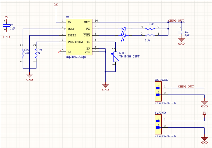
Hi, I've set up a test circuit PCB using the product noted above but can't seem to achieve the programmed charging current of 915mA.
My set up is as follows:
- The battery is an 18650 Li-Ion cell, 915mA charging current, 4.2V cell voltage.
- A DC power supply set to 5V, 1.2A is being used to source the circuit.
- A benchtop multimeter is being used to measure current between the OUT (pin 10) of the BQ24092 and the cell.
For the circuit
- ISET is pulled down via a 590Ω resistor to achieve 915mA of charging current. K(Iset) = 540 -> R=540/0.915=590Ω
- ISET2 is pulled down to ground to disable current limiting for USB source
- PG and CHG have LEDs and 1.5kΩ resistors pulled high to the OUT pin. Both are illuminated
- 10µF filter caps are used on IN and OUT of the IC
- An NTC (TH11-3H103FT) is used. Similar to the one in spec sheet. I've also tried pulling this to ground via a 10k resistor.
Things I've tried:
- The voltage at ISET is 1V. This should yield ~1A or so of current
- I've tried shunting the TS pin to ground via 10kΩ resistor. This did not change the behavior.
- I've tried removing the Ammeter, but the DC power supply only ever supplies 180mA, indicating that the circuit is only charging at ~170mA of current.
- I've built a separate circuit, using a breakout board for the BQ24092 IC. The same behavior was observed - indicating this isn't just a bad IC or bad solder joints.
Below is a screenshot of the circuit:


