This thread has been locked.

If you have a related question, please click the "Ask a related question" button in the top right corner. The newly created question will be automatically linked to this question.

BQ79616-Q1: Stacking for 32S and current sense ADC value using BBP and BBN pins

Part Number: BQ79616-Q1
Other Parts Discussed in Thread: BQ79616, TXS0102

Hi,

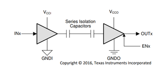
We're designing a system for 32S in which we've stacked two AFE's in daisy chain using capacitive coupling because both AFE's are on the same board.

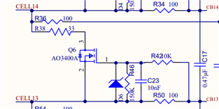
And also we're using external cell balancing in both AFE's to avoid temperature rise due to internal cell balancing.

The BBP & BBN pins are used to measure the voltage drop across the current shunt resistor through which the the ADC value will be used to interpret the current in the MCU.

There are 4 resistors of 2 milliohm equivalent to 0.5 milliohm and the voltage drop at max current is 300mV which is well below the prescribed limit of 800mV at these pins.

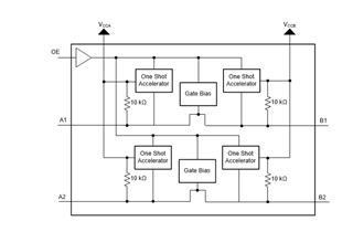
Request you to review the schematic especially the external cell balancing circuit as there is very little information provided about it and then the daisy chain connection and termination of COMLP, COMLN of the base device and the COMHP, COMHN of the top device and also the current sense circuit and its drawbacks if any when the current flow is in both directions.

Awaiting your valuable response.

Thanks & Regards

Ibrahim

32S BQ79616 BMS (REVIEW).pdf

  • Hi Mohammed,

    I recommend using the BQ79656 to monitor the current sense resistor. The BQ79656 is the same as BQ79616 except the busbar pins are replaced with current sense pins. Using the busbar to measure the current sense resistor would not provide as accurate of a result as the BQ79656.

    Regards,

    David

  • Thanks for your reply David.

    We're fine with managing the accuracy and also the current measurement through BQ79616 is additional option that we have along with a current sense amplifier too that we have which communicates the ADC value again with the MCU.

    Would like you to please give a feedback on the schematic as well for two AFE's stacked especially the following:

    1) The external cell balancing circuit as there is very little information provided about it and then the daisy chain connection and termination of COMLP, COMLN of the base device and the COMHP, COMHN of the top device.

    2) The importance of the Digital Isolator between AFE & MCU for communication through UART. As we have only two AFE's stacked we are considering to not use an isolator and have a common ground for AFE & MCU as the system is configured for high side switching only.

    Is the Isolation between AFE & MCU mandatory?

    Would greatly appreciate your response for the same. Please refer the schematic attached for your reference.

    Thanks & Regards

    Ibrahim Saqib

    32S BQ79616 BMS (REVIEW) (1).pdf

  • Hi Mohammed,

    The external cell balancing circuit as there is very little information provided about it

    The way the external cell balancing works is that two sources are sinking current from the battery: the internal IC CBFET and the external FET. 

    I will use CB14 to CB13 as an example. Cell14 is the voltage of 1 cell while Cell 13 is the cell's gnd reference. When CBFET14 is turned on, CB14 to CB13 will be connected together with a resistance of Rdson (described in datasheet). This creates a voltage divider between R50 and R34+Rdson. The equation for the voltage between R50 and Rdson is Vcell * R50 / (R34+Rdson+R50). R46 and R42 forms another voltage divider, but it is used to set the voltage of the gate to a known value. Setting the voltage of the gate to a known value helps in reducing spikes in the Vgs waveform. C23 forms a low pass filter with R42. The Diode is for protecting the FET from exceeding its rated Vgs value.

    The total balancing current = Iext_fet + Iinternal_fet

    Iext_fet = Vcell/(R38+Q6's Rdson)

    Iinternal_fet = Vcell/(R36+R50+internal IC's Rdson)

    then the daisy chain connection and termination of COMLP, COMLN of the base device and the COMHP, COMHN of the top device.

    This section looks correct.

    The importance of the Digital Isolator between AFE & MCU for communication through UART.

    The BQ79616 uses 5V UART logic. If your MCU supports 5V UART then an isolator is not necessarily required. If your MCU only supports 3.3V UART then the isolator is required.

    Is the Isolation between AFE & MCU mandatory?

    The isolation requirement is described above. It is not mandatory, but it can be common for protecting the MCU. Since the AFE deals with high voltage, it is up to the customer's discretion on whether an isolator would be beneficial for their application.

    Reviewing the schematic:

    Isolator:

    MCU's RX pin should be pulled up and the BQ79616's RX pin should be pulled up. Remove the 2 TX pin pull-ups.

    LDOIN-NPNB loop:

    Rnpn and the BCX56 transistor is fine. The capacitors are also fine.

    Power tree pins + references:

    The DVDD, AVDD, BAT, TSREF, CVDD, NEG5V, and REFHP capacitor values are fine

    VCCB section:

    No issues are seen on the VCCB section

    GPIOs:

    No issues are seen on the GPIOs section

    Regards,

    David

  • Thanks for the very detailed feedback David. Appreciate your valuable response.

    Understood all the points you made.

    One final thing i needed clarity on is as the need of the isolator between MCU & AFE is solely for the difference in logic voltages, is it fine to use a logic/voltage level shifter between the two like the TXS0102 from TI.

    Would like your view on the same.

    Thanks & Regards

    Ibrahim

  • Hi Mohammed,

    ISO7442:

    TXS0102:

    The issue with the TXS0102 appears to be that it has pulls up on both the RX pin and the TX pin which would not be recommended as the BQ79616's TX pin is already pulled up to CVDD. 

    Regards,

    David

  • Hey David, 

    Thanks again for your valuable response.

    If that's the case then using a logic level shifter without the internal pull-ups should do the job right?

    Thanks & Regards

    Ibrahim

  • Hi Mohammed,

    Yes, that should work.

    Regards,

    David