This thread has been locked.
If you have a related question, please click the "Ask a related question" button in the top right corner. The newly created question will be automatically linked to this question.
Tool/software:
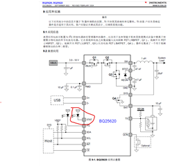
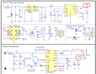
We have one new project used the charger IC model: BQ25620RYKR that for Li-ion battery quick charging management and in parallel with one linear charger IC model : BQ25170J. In the circuit that the BQ25170J can be working well with output current for 400mA approx. to battery charging. But the quick charger IC: BQ25620 cannot be working, and we design the schematic based on TI's datasheet and EVM user's guide also with the PCB Layout guidelines.
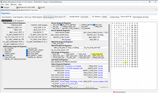
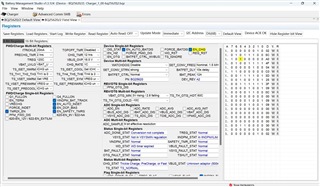
Meanwhile, we have fixed the BQ25170J and BQ25620 with full charging voltage are same with 4.4V, and I have also download the BQ studio tool for checking the BQ25620 circuit by setting some register parameters to check why BQ25620 not working, but I do not know how to use this tool for analyze the root failure and showing errors report since the BQ25620 EVM user guide just have described the simple building step based on the good BQ25620 EVM tool. could you please help to provide the user guide with more details of BQ25620 in BQ studio?
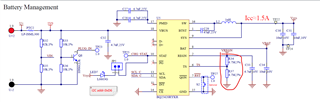
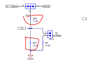
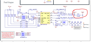
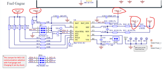
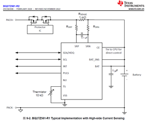
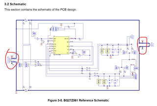
I have the main question/issue why the BQ25620 could not working? as we also used one TI's fuel gauge IC:BQ27Z561 for device battery SOC measurement. Could you please help to check the schematic is it correct?
How about the VBAT and VBAT_C network connection is it OK into the circuit design? since the fuel gauge IC and BQ25620 both used the I2C communication with one same MCU, when we download the FW into MCU, do we need to use the jumper connected all the I2C connector JP10 as schematic in shown? please find the attached schematic of BQ25620 and Fuel gauge IC:BQ27Z561 and BQ25170J circuit connection.
I am looking forward to your side professional answer and great support solution since it's very urgent for me to solve it ASAP, many thanks in advance.
Best regards,
Kevin WongSchematic_Sheet1.pdf
Hi Kevin,
It looks like the STAT pin of the BQ25620 may be damaged are there is no current limiting resistor. The max current for this pin is 6 mA. Please include recommended current limiting resistor of 10kOhm and replace IC.
If that doesn't work, please read all the registers using BQStudio and report them here. The User Guide is available on the BQ25620EVM Page: https://www.ti.com/tool/BQ25620EVM
I am looping in the gauge team so they can review the schematic for the gauge.
Regards,
Mike Emanuel
Hey Kevin,
I have taken a look at your schematic for the BQ27Z561-R2 gauge and I do not see any obvious issues here.
Regards,
Jonny.
Hello Mike, Noted and thanks for your checking. but your datasheet also mentioned this STAT pin have no current limit resistor. so I still have some questions such as below and help to get your great support and guidelines.
(1). For the BQ25620 with STAT pin, if the indicator LED burned, I will remove it and also will add in series with 4.7K ohm resistor, do you mean that if this LED burned will lead to the BQ25620 IC must be failed or burned?
(2). The TS pin of BQ25620 with two resistors is it correct? If I fixed the TS with fixed resistor like two 4.7M ohm is it OK? From the datasheet that I am not sure what I understand is it correct? as the datasheet mentioned it this TS pin need to setting it with 0 centigrade and 60 degrees? how could we evaluate it of the resistor value?
(3). as my schematic shown that have two charger IC in parallel, one linear charger is the BQ25170J and output the network with VBAT_C, the other one is the quick charger BQ25620 with connected with battery in network with VBAT, both network just have the Fuel gauge IC:BQ27Z561 sensing resistor of R45 with 2m Ohm. in this way the connection is it OK?
Could you please pass forward the attached schematic to your colleague checking with responsible for fuel gauge IC?
(4). I have also download the BQ studio tool for Charger registers checking, could you please help to check below items is it OK? or how can we use this
tool for testing? do you have the user guide for BQ studio charger part using? I am just refer to the BQ25620 EVM user guide for reference but I could not
know how to check it.
That's all and looking forward to your professional reply, thanks.
Kind regards,
Kevin Wong.
Hello Jonny,
For fuel gauge IC of BQ27Z561 circuit design that VBAT and VBAT_C network among the resistor of R45 with 2m Ohm. as you know that this VBAT_C network from the BQ25170J output side, and the BQ27Z561 fuel gauge IC POWER supply all from this VBAT_C network, if we do not use this BQ25170J linear charger IC, so how could we deal with this connection?
Moreover, for above schematic that I used High-side Current Sensing solution, what's the difference between High-side Current Sensing and Low-side Current Sensing? If I just use this fuel gauge IC into the main PCBA system side, not for assembled into Pack side, how could we create the SYS+ and SYS- connection into system side?
regarding to the EVM circuit that CELL+ and CELL- is it can be used for battery PACK+ and PACK- connection? please find attached schematic and how could we consider the network position VBAT and VBAT_C for charging or discharging sequence?
I am looking forward to your great support and can solve it, thanks.
Kind regards,
Kevin
How could I check the IC function is it working good with some pins configuration?
Hi Kevin,
1. The datasheet clearly lists the "Output Sink Current" for STAT in Section 7.1 Absolute Maximum Ratings. Putting too much current through this pin could damage the device.
2. Please bias the TS pin between the chosen TH3 and TH4 thresholds. This will vary depending on the chosen registers settings. Check out the EC table for TS_PRECOOL and TS_PREWARM thresholds.
3. I would check with Jonny, but I do not believe it is right for BQ25170 to bypass the sense network.
4. There is no User Guide for the BQZ specifically. Please refer to the register settings in the BQ25620 datasheet in order to set the setting appropriately. You should be able to see some basic status based on just powering it on. You will need an EV2400 to evaluate it.
Regards,
Mike Emanuel
Hello Kevin,
For the BQ27Z561, the BAT_SNS pin should be connected directly to the battery positive connection, and the BAT pin should also be connected directly to the battery, and these two pins should not share the same path.
The sense resistor for the fuel gauge should not be bypassed in the design.
For the difference between high-side and low-side current sensing, I recommend referring to this document: System Trade-offs for high-side and low-side current measurements.
Regards,
Jonny.
Hello, yes, since the STAT status LED indicator if without the current limiting resistor that it will blinking for several seconds then died.
If we choose the TH3 and TH4 thresholds, how could evaluate the RT1 and RT2 resistor value?
I have already used the EV2400 tool and will share the chargers setting pictures later.
Hello Jonny, I will remove the PTC1 and keep it not assembled, so can we use the VBAT_C with connected to battery PACK+ via shunt resistor/current sense resistor R45 then returns to connected VBAT network of BQ25620 BAT pin in high-side current sensing solution, is it correct?
Best Regards,
Kevin
Hello Michael,
please find below charger filed view of BQ25620 but it still have some errors.
How could I deal with it? thanks.
Hi Kevin,
It is required to have the current limiting resistor. The device may be damaged without it.
Please see Section 8.3.5.4.2 TS Pin Thermistor Configuration to calculate RT1 and RT2. Also the calculator here will help: https://e2e.ti.com/support/power-management-group/power-management/f/power-management-forum/1209815/faq-bq25620-bq2562x-calculator-tool
You are in TS_HOT. Please adjust your TS divider.
Regards,
Mike Emanuel
Hello, Michael. as you can see my previous message that I used the TYPE C with DC5V, so I am just in series with 330Ohm for STAT pin current limiting resistor and the LED7 will blinking without battery condition. If we in series with 10Kohm that LED working current with lower than 1mA so the LED7 indicator with much less brightness. please find the attached video if added the current limiting resistor and LED7 for STAT pin will blinking that means the IC still can be working, right? it still not be damaged, right?
For the TS pin of Thermistor Configuration to calculate RT1 and RT2. Could we replace the 4.7Mohm to 5.1k OHM and 30k OHM directly into my circuit application?
I am sorry that I still not understand the calculate formula that you shared the sheet. many thanks for your support.
Kind regards,
Kevin Wang
Hi Kevin,
As long as the 6 mA threshold is not exceeded you should be fine.
Please pay attention to the datasheet. It provides the level for the various TS conditions. If you do not want to use a thermistor, you can just disable TS in the register map and not have any resistors at all by REG0x1A bit 7.
Regards,
Mike Emanuel
Hello, I have replaced the two 4.7M ohm with 5.1K ohm and 30K ohm// 10K ohm and it can be charging now. the BQ Studio with Charger field view TS normal showing as below.
I have also checked the BQ27Z561 with Fuel Gauge application. the gauge window showing the battery charging current is 1100mA approx. But the digital multi-meter measured the current just for 550mA approx. and the Gauge window showing the current polarity with negative direction. Why the fuel gauge measured the charging current with 2 times for real current value and have the opposite direction?
Could you please help to push this Fuel Gauge issue to your professional colleague to check it? thanks.
Kind regards,
Kevin Wang
Hello Kevin,
What is the sign of the CC Gain parameter? Have you performed current calibration on the gauge? Additionally, are you able to use your multimeter to measure the voltage drop across the sense resistor, then use ohms law (with the value you have for the sense resistor) to calculate the current that is seen by the gauge?
Regards,
Jonny.
Hello Jonny, As this project that we used the Fuel Gauge IC into my Main Board with System side, not for Pack side. I still not preformed the calibration.
the voltage drop between sense resistor value is 2.58mV-2.6mV. Did you have the Fuel gauge of BQ studio quick user guide?
why the BQ studio of Gauge showing the current with negative direction and have 2times ?
Hello Kevin,
The BQ27z561 User's Guide can be found here. A possible reason the gauge is reporting negative current when charging is due to a negative sign for the CCGain parameter.
Regards,
Jonny.
Noted and I will double check it. do you have the Fuel gauge setting of BQ Studio user guide? thanks.
Hello Michael, do you have the STAT pin with charging error information report? or it means that different error with different status.
Do you have the BQ Studio of Charger setting user guide?thanks.
Hi Kevin,
Table 8-5 of the datasheet clearly lists the state of the STAT pin under different operating conditions. Please refer to this and the datasheet as a whole.
As stated earlier, there is no User Guide for the BQZ specifically. The settings you make will depend on your operating requirements. Please remember to disable the watchdog if not intending to overwrite it.
Regards,
Mike Emanuel
Hey Kevin,
I am not sure what you are asking for here, can you please elaborate?
Regards,
Jonny.