This thread has been locked.

If you have a related question, please click the "Ask a related question" button in the top right corner. The newly created question will be automatically linked to this question.

BQ76952: CC3 ADC counts keep changing and is not linear with the voltage across shunt resistor.

Part Number: BQ76952

Tool/software:

Hi,

I am using BQ76952 using I2C communication. I am using 0.5mOhm shunt resistor (1mOhm X 2 resistors in parallel). I am trying to read CC3 ADC counts for currents 5 A and 10 A and I am finding that it is not varying linearly with the Voltage across shunt resistors. Also, many times when I turn on and off the system, I find the CC3 current count range is shifted. I am using default 80 samples for averaging the CC2 count in CC3. 

I am getting CC3 counts as following

CC3 Count Voltage(mV) across Shunt resistor Current(A)
11900 1.1 2
52700 2.1 4
67400 2.7 5
84600 3.2 6
108000 3.5 7.3
173000 5.1 10

I am using following setting for gain callibratition. But due to this CC3 values, the current values are also not correct.

Cc gain=(7.5684/Rsense)=(7.5684/0.5)=15.1368
Cc gain (float to hex)=0x41723055
Capacity gain= Cc gain * 298261.6178= 15.1368* 298261.6178=4514726.4563
Capacity gain (float to hex)= 0x4a89c74d

  • Hello Swapnil,

    What is the CC2 measurements here?

    If you take multiple CC2 and CC3 measurements over time at each temperature, does it change? I am wondering if maybe the IC heats up.

    Best Regards,

    Luis Hernandez Salomon

  • Hi Luis, 

    Thanks for responding!

    CC2 measurements are same as CC3. Just that the CC2 measurements are fluctuating and CC3 is more stable.

    If I take multiple readings of CC2 and CC3 over time, it does not change. It only changes if the power is shut down and started again. Even if we do it within a few seconds it changes. 

    I will check IC temperatures and revert back. 

    Also, I am testing the PCB with Higher current to check if issue is because of very low voltage across shunt resistor. It is around 5mV of 10A. 

  • Hello,

    I am out of office until Wednesday. Responses will be delayed until then.

    Best Regards,

    Luis Hernandez Salomon

  • Hello Swapnil,

    How does it change after the POR? I am very curious on that regard.

    Do let us know the IC temps and currents and if it affects anything!

    CC2 is likely fluctuating just due to offset error, which should be mostly removed in CC3. Does the current reported match what it should be drawing in your application? What is the measured resistance of your shunt resistor?

    Best Regards,

    Luis Hernandez Salomon

  • Hi Luis,

    Thank you for your valuable support!

    values do not change after POR. they remain the same.

    However, we could identify the issue. The sense track was carrying current for some other circuit. We separated the track for that circuit, and we could get correct readings. the readings do match to actual current. However, there is error of around 2-3%. We were thinking if there is any method of removing the error. 

    Is there any method we can compensate the tolerance of sense resistor? this will be required and performed in EOL testing.

  • Hello Swapnil,

    Glad to hear that was figured out Slight smile.. 

    To get the most accurate current measurements, you can perform a two-point calibration to calibrate your device. Steps for this can be read in Section 2.6 Current Calibration of the BQ769x2 Calibration and OTP Programming Guide.

    This likely would give you the best accuracy possible, I would suggest to attempt this and see how much the current measurement improved.

    Best Regards,

    Luis Hernandez Salomon

  • Hello Luis,

    Thanks for providing the link for calibration guide. This resolves my issue as I can calibrate the readings as per the instructions given in this document. I will first try this out manually and get back to you. If successful I will be implementing auto-calibration at EOL.

    Is there any such guide or document to work with accumulated charge registers in data stratus 6? I am seeing that if I read this register continuously, it resets to 0 after random period between 10 to 20 Seconds. also, the values are also irrelevant and continuously fluctuating rather than accumulating. means I can get one value positive and the next value negative.

  • Hello Swapnil,

    No problem Slight smile.

    We do not have a document showing the accumulated charge feature.

    Do you have any logs of this? Is there any charging or discharge current? Has there been a partial reset?

    Best Regards,

    Luis Hernandez Salomon

  • Hello Luis,

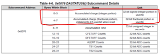
    I was trying to read following register.

    This is byte 0-3 and  4-7 of the 0x0076 DATASTATUS6() subcommand.

    I will take a log and provide the same. do you suggest not to use this register for SOC calculation? We had planned to rely on this register for SOC calculation so that MCU can be in sleep while in idle mode. otherwise MCU has to continuously keep a track of current.

  • Hello Swapnil,

    For accumulated charge, this is the register you would want to use and we do recommend to use it for this type of application. 

    Do let me know of the logs! I'd definitely like to know what is going on there, so a log may shed some light on what is going on. Additionally, the test conditions for when you are testing this would also be great to know! 

    Best Regards,

    Luis Hernandez Salomon

  • Hi Luis,

    I am facing some issues related to I2C communication. I2C communication gets hanged with SCL line pulled low after 10 to 14 Seconds. So we are resetting the I2C communication by setting the RST_SHUT pin low for less than a second. and then restart the communication again. In this process, I am doubting, that the Accumulated charge and accumulated charge time also set to 0. 

    Is there any Way to know why AFE I2C gets hanged? It is not hanging on any particular command and does hang on randomly any command. We have set the delay of 5 millisecond between any I2C transaction including different commands and dummy write and read cycle of single command. 

    Can you guide to debug this issue.

  • Hello Swapnil,

    Does your MCU support clock stretching? The BQ76952 will perform clock stretching when it needs to. If your MCU does not support it, there may be issues with the communication.

    That would be my first guess on why it would hang.

    Accumulated charge and accumulated charge time also set to 0. 

    Correct, a partial RESET will cause these to be reset and will need to be re-initialized. See Section 3.9 Why is the accumulated charge measurement seems to be producing an incorrect value? of the BQ769x2 Frequently Asked Questions document.

    Best Regards,

    Luis Hernandez Salomon

  • Good Morning Luis,

    Yes, MCU supports clock stretching. it also works for 10 to 12 seconds. I am scanning all the read values continuously. for a single scan it approximately takes 100mSec. I earlier had doubt that MCU I2C bus is failing, But It is not coming out of the fault status even if the MCU I2C peripheral is reset. AFE Partial reset is only option to reinitialize the communication.

    Is there any way to reset only I2C communication?

    Is there any requirement to ensure the reliable functionality of the I2C communication? 

  • Hello Swapnil,

    The clock being stuck low is not very common for this device, so I am surprised it is happening here. MCU's that cannot support clock stretching is when things do not go well.

    We have seen cases where SDA seems to be stuck low, but that is easily fixed by sending 9 clock signals. For cases where SCL is stuck low, then the partial reset is really the only way to possibly release it. Unfortunately.

    Do you happen to have logic analyzer captures when this happens? Additionally, could you share your BMS schematic so I may review this?

    Best Regards,

    Luis Hernandez Salomon

  • Hello Luis,

    Thanks to your direction, We could Identify the I2C hang issue. Our Clock was 444 KHz instead of 400 KHz. when we changed the same, I2C stopped being Hanged. And as a result, we can now have the accumulation time which is not resetting to 0.

    We will now put the system in load setup to test the code for Accumulated charge calculation. Thanks for your support