This thread has been locked.

If you have a related question, please click the "Ask a related question" button in the top right corner. The newly created question will be automatically linked to this question.

BQ24650: Prevent BQ24650 leakage current (SLVA829)

Part Number: BQ24650
Other Parts Discussed in Thread: BQ40Z50-R2

Tool/software:

Hi,

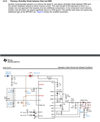
What are the alternatives to the diode indicated in the SLVA829 document?

The use of a diode with high load currents has too high a thermal dissipation.

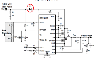
What solutions are there to protect the BQ24650 from a solar panel connected with reversed polarity, other than the obvious one of using a diode?

thanks.

regards

Jose

  • Hello Jose,

    I found a similar question that you posted a few months ago BQ24650, I saw that Jeff suggested using multiple diodes in parallel, did this soultion have any affect on the thermal dissipation issue?

    Best Regards,

    christian.

  • Hi Christian,

    Thank you for your reply.
    Due to the limited space available on our board, the suggested solution was not suitable.

    In the meantime, we have developed a circuit, which we have tested in the laboratory using a solar panel simulator and a battery simulator.

    After detailed testing, data collection and analysis, we concluded that the circuit's performance is exceptional.

    However, when we placed the PCB in an outdoor test system with a solar panel and battery, the charge never started!

    We went back to the lab and used the same real battery that we were using in the outdoor test system, and a solar panel simulator, and different types of power supply as an alternative to the solar panel simulator - it works perfectly.

    We can't understand what's going on ... and why it works exceptionally well in the laboratory and doesn't work with a solar panel.

    Could I send you the circuit in a private message, so that you can give your opinion of what's going on, and why the bq24650 never starts charging.

    regards

    Jose

  • Hello Jose,

    Yes, I sent a friend request on E2E and you should be able to connect with me and send a private message, or you can send the schematic to my email. c-moyer@ti.com

    Best Regards,

    Christian.

  • Hi Christian,

    Thank you for your reply, and I've already sent you an e-mail with the schematic drawing and a description of the problem. 

    regards

    Jose

  • Hello Jose,

    I'm reviewing your schematic, and will provide an update by EOD Tuesday.

    Best Regards,

    Christian.

  • Hello Jose,

    In the condition of the battery not being charged, What is the voltage on the MPPSET pin?

    Best Regards,

    Christian.

  • Hi Christian,

    In order to carry out a proper test, we put the board in the outdoor test system last night.
    This morning, after several hours of intense sunshine on the solar panel, we took the measurements below.

    Vsp = 21.77V (voltage at Mosfet Source Q3A - Solar panel voltage)

    Vin_mppt = 21.74V (voltage at Mosfet Drain Q3A)

    Vmppset = 1.510V (voltage at MPPSET pin)

    Vref = 3.296V (voltage at VREF pin)

    Vts = 1.912V (voltage at TS pin)

    Disconnecting the positive cable from the solar panel and connecting it immediately , the BQ24650 starts working
    The battery starts to charge and everything works as expected.

    Vsp = 17.36V (voltage at Mosfet Source Q3A - Solar panel voltage)

    Vmppset = 1.197V (voltage at MPPSET pin)

    I hope this data helps you understand where the problem might be.

    regards

    Jose

  • Hello Jose,

    What is MPPT_SHDN? Is this pulled up by the VREF pin?

    Best Regards,

    Christian.

  • Hello Christian,

    The MPPT_SHDN (RG6) label is connected directly to a microcontroller output. We use this signal to shut down the BQ24650 in versions where the MPPT charger is disabled.


    In the previous version we used this signal to shut down the BQ24650 when the solar panel voltage was between Vmp and Vbat, thus preventing the BQ24650 from consuming battery reverse current.

    regards

    Jose

  • Hello Jose,

    I have a few suggestions to try:

    Can you re-run the test with R29 tied to Vref?

    What are you using as the battery? have you tried using a different battery or battery simulator

    The next step is replacing the IC. Your team measure Vmppset = 1.510V when the board is not charging, the device should regulate this voltage to 1.2V. This could indicate the IC is damaged.

    Best Regards,

    Christian.

  • Hello Christian,

    What is the purpose of your suggestion to connect R29 to Vref?
    If we connect R29 to Vref, which is 3.3V, the Mosfet will be ON, the MPPSET pin connected to GND and the BQ24650 will be in shutdown. What can we conclude?

    Please note the following:


    Whenever we used the battery simulator and the solar panel simulator, the BQ24650 worked correctly.
    When we used the solar panel simulator and a battery, it also worked correctly.
    We used several batteries, including the one that was in the test system outdoor - always works under these conditions.

    We tested it on 4 different boards, and on all 4 boards the symptom is the same, it works correctly in the laboratory, and it doesn't work outdoors with the solar panel.

    As I've already mentioned, after hours of exposing the solar panel to the sun, and without BQ24650 starting to charge, all we have to do is remove the positive cable from the solar panel, and plug it back in immediately, and the BQ24650 starts working properly.
    After that, the voltage on the MPPTSET pin goes from 1.510V to 1.197V, i.e. the expected 1.2V.
    From then on it works properly..

    If we set R6 = 0 ohm, shunting the diode that isolates the BQ24650 circuit from the battery, the BQ24650 works as expected.

    We don't see how the BQ24650 could be faulty, when it works well under the conditions described above, and equally well on 4 different boards.

    regards

    Jose

  • Hello Jose.

    If we set R6 = 0 ohm, shunting the diode that isolates the BQ24650 circuit from the battery, the BQ24650 works as expected.

    To clarifiy, If you remove the ideal diode that isolates the BQ24650 circuit from the battery, you are able to start charging in the morning without reconnecting the adapter?

    Is there a reason you can not remove this ideal diode?

    Best Regards,

    Christian

  • Hi Christian,

    I can confirm that if the ideal diode is removed, or a shunt made via R6, the circuit works without any problems.

    The reason we use the diode is exactly to prevent reverse current from the battery, as described in the TI document - Prevent BQ24650 leakage current (SLVA829).

    Do you have any idea what might be happening, and why the diode is giving problems?

    regards

    Jose

  • Hello Jose,

    The reason we use the diode is exactly to prevent reverse current from the battery, as described in the TI document - Prevent BQ24650 leakage current (SLVA829).

    Your schematic shows two ideal diodes, one at the input and one at the output. These two diodes are serving the same purpose of blocking reverse current. In the app note It shows to remove the input diode if you are going to be using one at the output. So I recommend removing this diode.

    Do you have any idea what might be happening, and why the diode is giving problems?

    We have not ran into this problem before, so I can't give an exact reason on why this is giving a problem. I think the issue is using both diode, one at the input and one at the output. Another test to try is to shunt the input diode and keep the output diode and see if are still seeing the same issue. 

    Best Regards,

    Christian.

  • Hello Christian,

    The diode next to the solar panel is intended to protect the circuit from the solar panel being connected with reversed polarity, and it works well.

    If this diode next to the sola rpanel is removed, and only the diode next to the battery is kept, the circuit will not work properly.
    This is actually the concept of the SLVA829 document, but it doesn't work with the ideal diode.

    Our tests clearly show that the problem is only solved when we remove the diode next to the battery, and therefore lose the functionality of preventing reverse current from the battery through the BQ24650. In fact, that was the only purpose for which we used this diode.

    If you don't have any other suggestions, and considering that we can't figure out why the diode next to the battery is causing problems, we'll just have to abandon the circuit and find another alternative.

    So we'll wait for your final comments in order to make that decision.

    regards

    Jose

  • Hello Jose,

    I'm discussing this issue with another team member, to see if we have a work around.

    In the app note you mentioned, the diode off of SRN  is used to prevent leakage current. The app note mentioned in order to use this method, diode1 has to be removed. That is why I suggested removing the input diode.

    The diode is also required to be placed between the SRN pin and the resistor feedback network, but on your schematic the diode does not seem to be connected to the resistor feedback network.

    Best Regards,

    Christian.

  • Hi Christian,

    Yes, you're right, we have the diode just before the battery, and not between the SRN pin and the feedback loop.
    We didn't think it would make a difference.

    It's quite easy to rework the board and change that connection, so we're going to do it and test it.
    We'll get back to you as soon as we have results.

    regards

    Jose

  • Hi Christian,

    We reworked the PCB slightly and connected the Vfb feedback loop directly to the Mosfet's Drain instead of the Mosfet Source (original circuit).


    In laboratory tests with a battery simulator and a solar panel simulator, everything worked as expected.

    Outside, with a solar panel and a battery, the circuit behaved in the same way as before.
    In other words, the panel maintained a voltage of around 22V for 3 consecutive days, and never charged the battery.

    All we had to do was disconnect the positive terminal of the solar panel and reconnect it immediately, and the battery started charging straight away.

    From this we can conclude that the behavior of the circuit with the change in the Vfb loop is the same as with the original circuit.

    I wonder if you have any suggestions for an additional test, otherwise we'll have to abandon the circuit because of the delays this problem has introduced into the project.

    regards,

    Jose

  • Hello Jose,

    The BQ24650 is a legacy device so I can only go off the limited information that we have. The SLVA829 document states that the input diode needs to be removed and a schottky diode placed between Vbat and SRN. We do not have any information on why the input diode has to be removed and why the output diode has to be a schottky. This configuration has not been evaluated with an ideal diode, so we can't guarantee normal operations under all circumstances.We've tried to find a work around, however this ideal diode is causing unexpected behavior with the BQ24650. My only recommendation is to follow the app note and remove the input diode and use a Schottky diode at the output, but based on previous replys this is not possible.

    Best Regards,

    Christian.

  • Hello Christian,

    Thank you for your reply,

    We removed the diode next to the battery and put a Schottky diode next to the solar panel, and the BQ24650 worked correctly, with good charging performance. This is the original circuit suggested in the datasheet.

    We tested it with a solar panel simulator and battery simulator, and later outdoors with a solar panel and battery - everything works as expected.


    In the meantime, we have another problem that you might be able to comment on to understand why it's happening.

    In the project there is a specific specification that the solar charger must charge a lithium battery when it is completely discharged and has zero volt.
    The zero volt in the battery happens when the BMS disconnects the battery to protect it.

    We discharged a battery in an electronic load to 0V and used it with the BQ24650 and a solar panel simulator, and it charged correctly.

    We discharged the battery again and placed it in the outdoor test system with a solar panel.

    Here the BQ24650 never started charging and throughout the day of intense sunshine it kept the solar panel at around 22V, i.e. it never fixed the voltage of around 17V which is the solar panel's Vmp. It never started charging!

    What can we do to overcome this problem?

    Is there an alternative component to the BQ24650 that does not have the above problem, and does not allow battery current when the solar panel is shaded?

    regards

    Jose

  • Hello Jose,

    Is this issue related to the diode? Do you still see this issue when you shunt the output diode?

    Best Regards,

    Christian.

  • Hello Christian,

    It has nothing to do with the diodes as they have already been removed, and we are now using the reference circuit from the datasheet.

    Does the BQ24650 need to have battery voltage to start charging, or should it start charging with a battery that has zero volt?

    regards,

    Jose

  • Hello Jose,

    It has nothing to do with the diodes as they have already been removed, and we are now using the reference circuit from the datasheet.

    Yes, I understand. I just wanted to know if the schottky diode could be causing this issue. The reference circuit was designed to work in most circumstances, but I am unaware if this includes Zero volt battery.

    Does the BQ24650 need to have battery voltage to start charging, or should it start charging with a battery that has zero volt?

    The BQ24650, should be able to charge a zero volt battery.

    I found a battery pack manager:BQ40Z50-R2. I do not support this device, but I have seen other post related to Zero Volt charging, and this device is used to help start charging when battery is at 0V.

    I recommend posting a new question related to this device to see if this could resolve your current issue.

    Best Regards,

    Christian.


  • Hello Christian,

    Thank you for your reply indicating that the BQ24650 should start charging with a zero volt battery, and for your additional suggestion.

    Returning to the question of diodes, and before closing this support request, I would like to know if we can use a body diode from a Mosfet in D1, just to start the charge.


    Obviously the voltage drop will be higher than with a schottky diode, but it will only be used to start the charge, and then removed from the circuit when the charge is already active.


    Is this concept valid?

    regards

    Jose

  • Hello Jose,

    Returning to the question of diodes, and before closing this support request, I would like to know if we can use a body diode from a Mosfet in D1, just to start the charge.

    Yes, this should work.

    Best Regards,

    Christian.

  • Hello Christian,

    Thank you for your comments, so we will continue testing our circuit in order to find a final solution.

    regards

    Jose


  • Hello Christian,


    We've finished a set of tests and have concrete results, and I can assure you that the BQ24650 doesn't start charging on a fully discharged battery (zero volt).

    To make it clearer, I'll describe the totality of the tests carried out below.

    We produced an electronic controller with the BQ24650 and laboratory tests showed very high performance.

    Our circuit is similar to that of the EVM board, except that we don't use the VSYS output, but only the battery connected to VOUT and PNGD.

    All the electronics are connected to the same terminals as VOUT and PNGD, including a 3.3V regulator and a microcontroller.

    As I said, all the laboratory tests were excellent, having used a solar panel simulator and a battery simulator.
    Likewise, in an outdoor test, with a real solar panel and a battery, the results were also excellent.

    Finally, we carried out a test relating to a specification of the project, which is to charge a fully discharged battery with zero volt.

    To do this, we discharged a 12.8V lithium battery in an electronic load, until the BMS cut out, and the battery output was at zero volt.

    We placed this battery outside with the solar panel, and found that it never started charging.
    We repeated the test on consecutive days and the same thing happened every time.

    We went back to the lab and set up the solar panel simulator for the early morning solar conditions, and used the discharged battery.

    We found exactly the same thing, i.e. the charge doesn't start.

    We concluded that if we limit the solar panel's initial current to less than 15mA, charging never starts. What's worse is that if we then remove the current limitation, the BQ24650 never starts charging again, and stays in that state forever!

    The only way to get the charge started is to make a quick shunt between MPPTSET and Gnd.

    We initially thought that the problem was in the battery's BMS, so we used fully discharged supercapacitors as an alternative to the battery.

    The result was the same.

    We checked with the oscilloscope what signal we have at VOUT, and found that the voltage oscillates between 4.166V and 5.766V


    Our problem is that if the charge is not started we have no power to start the microcontroller, and therefore we have no way of making the shunt in MPPTSET that would solve the problem.


    Using the EVM board concept (using VSYS) isn't feasible for us, as all the electronics don't support more than 18Vdc.

    Designing an independent circuit to manage this problem, and making the necessary shunt to the MPPSET to start the charge, will increase the cost of manufacturing the circuit, as well as the area of the circuit, which we don't have the space for.

    We have no doubt that the charge is not initiated by the BQ24650 under the conditions described above, so we are looking for suggestions on how to solve the problem described.

    Thank you in advance for your comments.

    regards

    Jose

  • Hello Jose,

    Unfortunately I do not have any sugestions to resolve this issue that would not take up space or increase the cost of manufacturing of the circuit.

    My only suggestions would be to use the independent circuit that you mentioned above or  look into to useing the BQ40Z50-R2 for zero volt charging.

    I found a battery pack manager:BQ40Z50-R2. I do not support this device, but I have seen other post related to Zero Volt charging, and this device is used to help start charging when battery is at 0V.

    Best Regards,

    Christian.

  • Hello Christian,

    Thank you for your reply.

    The BQ40Z50-R2 is for designing BMS's for battery management, which is not our case - we don't manufacture battery packs.

    So from your answer I have to conclude that there is no solution for the BQ24650 to charge a battery with zero volt, except by implementing external control to the BQ24650.

    Best regards

    Jose