This thread has been locked.

If you have a related question, please click the "Ask a related question" button in the top right corner. The newly created question will be automatically linked to this question.

BQ25798: BQ25798@

Part Number: BQ25798

Tool/software:


Hello Jeff,
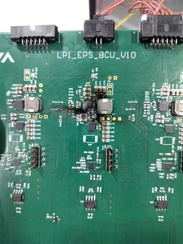
While using the BQ25798 IC for our application as MPPT , we come across the misbehaviour many times and the IC got burned with actual fire 3 times.
I hereby attached the Picture of the burned IC.
The setup has been described below:
-> Connected the 4s batteries(at 15.67V) with multimeter in series as a load at the VBAT side(Output of the BQ2578 IC) for charging purpose. Found that the batteries were providing the current of 34mA.
-> The batteries were not hot plugged(hence in the sequence , we connected the batteries first).
-> Connected the Power supply at 5V at 1A current limit from the PV side (input of the BQ25798 IC).
-> Once the power gets on from the source side the IC starts burning with fire.
-> We disconnected the supply and found that the batteries were still supplying the current of around 230 mA to the board.

This above setup is applied on other circuit also but on that it works well and charging but with some IC circuitary it is burning and the misbehaviour is observed.

I request you to please arrange a meeting with us in order to have the discussion on this issue as we need to use the IC in bulk for our application in space. We cannot take the risk like this , and also we need to actually figure out the exact cause of the same.
  • Hello Poori,

    Can you provide your schematic and PCB layout?

    Best Regards,
    Jibin.

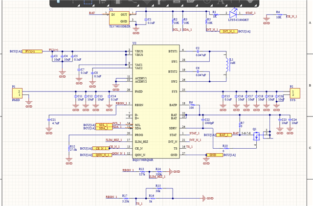
  • Schematic:

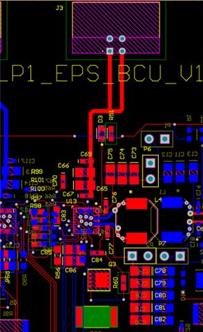
    Layout:

    Thanks & Regards

    Poorti Varshney

  • Hello Poorti,

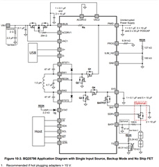
    The VAC1 and VAC2 should be shorted based on this:

    and recommend back to back ACFETs for reverse current protection and Note 1 in the typical application as the adapter is being hot plugged >15V.

    Best Regards,

    Jibin

  • Hello Jibin,

    Thank you for your suggestion but I have some doubt:

    1. If we short the VAC1 & VAC2 in the schematic shared with you and remove the capacitor , would it resolve the issue?

    2. I want to know the context behind the hot plugged as in our application the input would be the solar panel and it must not be hot plugged. Still we should include the ACFETs?Also if you explain the hot plugged!

    Thanks & Regards

    Poorti Varshney

  • HI Poorti,

    Regarding 1, I don't think having VAC2 connected to a cap instead of VAC1 will damage the IC but haven't tested it.  I have had other customers connect VAC2 sense to an arbitrary voltage and then use the ADC to measure that voltage.  

    Regarding 2, "hot plug" on the VBUS pin is when a power source with low output impedance is attached and line inductance causes ringing up to 2X the applied voltage.  Since input is a solar panel with high output impedance, hot plugging on VBUS is likely not the issue. Hot plug on the BAT/BATP pin means a fully charged battery or battery simulator is connected, causing the same ringing.  The BAT/BATP pins are only rated for 20V and damage at 21V. This could be your issue.  I strongly recommend adding a TVS zener diode to protect BAT/BATP if no shipFET is installed or a 33nF-47nF capacitor from BATP to GND if shipFET is installed to protect against hot plug.  The latest datasheet application diagrams and EVM user guide schematics highlight this.

    On the schematic, I see SDRV connected with 1000pF to BAT and also driving the gate of the FET?  If FET is not installed, SDRV should connect through 1000pF to GND (or floating) not BAT. This could also be the cause of the damage since V(SDRV) = 5V+voltage at BATP.

    On the layout, the traces to PMID and SYS caps must be much thicker than shown.  Also, it appears that the SWx traces via down to internal/bottom layer then back up to inductor as recommended.  But the PMID and SYS 0.1uF capacitors need to be flipped so that their GNDs almost touch and connect directly to the IC GND pin.

  • Hi Jeff,

    Thank you for your advice on VAC1 & VAC2.

    Also, thanks for clearing up the doubts about hot plug. Since we're using solar panels as the power input, we won't need to add the ACFET_RBFET circuit for reverse current protection. However, I'd like to know what additional precautions we should take for the initial tests using a DC power supply (at 17.5V) before moving on to tests with solar cells.

    Following your suggestion, we'll replace the 0-ohm resistor (R7 in the schematic) with a TVS Zener diode and skip using the shipFET. Additionally, we'll connect 1000pF to GND to maintain consistency with the schema of not including the shipFET. We'll also ensure to implement your recommendations regarding the traces in the revised version of the board.

    I have a few more questions regarding the design:
    1. In our design we used 5 such circuit of BQ25798 for individuial solar panels but all 5 circuit are parallely performing the charging of the batteries so is there any other protection apart from the zener diode that we should include in order work ideally.As when we were doing the individual test of the circuits , we observed different output voltage and charging current for the batteries /Battery simulator setup.
    2. In our design, both the load and batteries are directly connected to the VBAT net, with no load on the VSYS. Could this setup create any issues?
    3.During testing, we found that in some circuits, we initially didn't get voltage at REGN but did get voltage at PMID. After resoldering, we did get voltage at REGN. We suspect this is a soldering issue rather than a technical one. Could you provide your perspective on this matter?

  • Hi Poorti,

    1. Are all 5 BQ25798 connecting to 1 battery pack? Or 5 individual packs? If they are connecting to 1 battery pack, then you will need to use one charger as the main charger to deal with termination.
    2. I don't see any obvious issue. But Is there a particular reason why the load isn't on VSYS
    3. This is most likely a soldering issue, however the conditions to power the REGN LDO is:


    Best Regards,

    Jibin 

  • Hello Jeff,

    Thank you for the suggestions, but I request if you could please elaborate the point 1 , as what do you mean by the main charger and this termination.

    There is no particular reason behind not putting any load at VSYS, but the revised design we could think to put some load at the VSYS.

    Thanks & Regards

    Poorti Varshney

  • Hi Poorti,

    If there are 5 BQ25798 connecting to 1 battery pack, then you will have to select one of the 5 to deal with termination. 

    Best Regards,

    Jibin