


Other Parts Discussed in Thread: UCC28180
Tool/software:
Dear TI Team ,
We are using ucc256601ddbr LLC controller with ucc28180 PFC controller for 1k.watt 64V -15.6A EV charger (48v battery).
design is in in HF burst up to 6A, and when we put load 7A the output voltage decreases.
for reference i am attached some waveform like without load and with load of 5A
i am attached schematic and tool also, please provide solution or suggestion asap
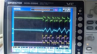 <------- without load , Ch4- green waveform is feedback, CH 2-blue waveform is ISNS , CH1 - yellow is low side gate, CH3 -pink is high side gate
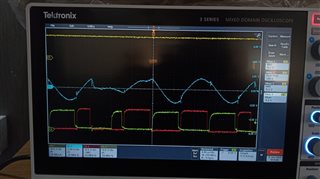
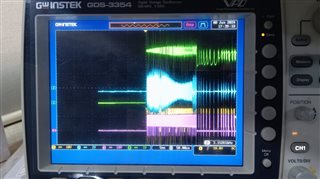 <------ with trigger mode, Ch4- green waveform is feedback, CH 2-blue waveform is ISNS , CH1 - yellow is low side gate, CH3 -pink is high side gate
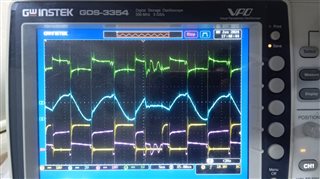 <------- with 5A load, Ch4- green waveform is feedback, CH 2-blue waveform is ISNS , CH1 - yellow is low side gate, CH3 -pink is high side gate
final UCC25660x_CALC_1.0 (2)( 64v15.6A)1000 watt_1805.xlsxPFC dsn.pdfLLC dsn.pdfPOWERSUPPLY dsn.pdf

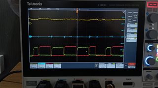 <----yellow Ch1= feedback , RED CH3= high side gate, Green CH4= low side gate , this waveform at load 6A and output voltage is 64.3v
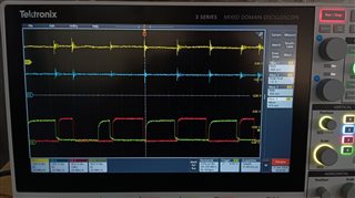
 <----yellow Ch1= IC VDD pin, blue Ch2=ISNS, RED CH3= high side gate, Green CH4= low side gate , this waveform at load 6A and output voltage is 64.3v
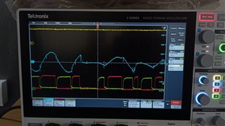 <----yellow Ch1= IC VDD pin, blue Ch2=ISNS, RED CH3= high side gate, Green CH4= low side gate , this waveform at load 8A and output voltage is 61.0
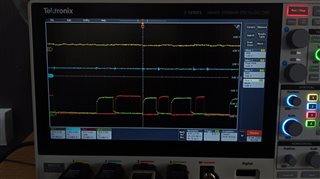 <----yellow Ch1= FB pin, blue Ch2=BLK, RED CH3= high side gate, Green CH4= low side gate , this waveform at load 8A and output voltage is 61.0
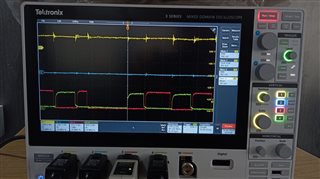 <----yellow Ch1= LL pin, RED CH3= high side gate, Green CH4= low side gate , this waveform at load 8A and output voltage is 61.0